GE Power Management
MM2 Motor Manager 2 6-41
6 COMMUNICATIONS 6.6 DATA FORMATS
6
6.6 DATA FORMATS 6.6.1 DATA FORMATS TABLE
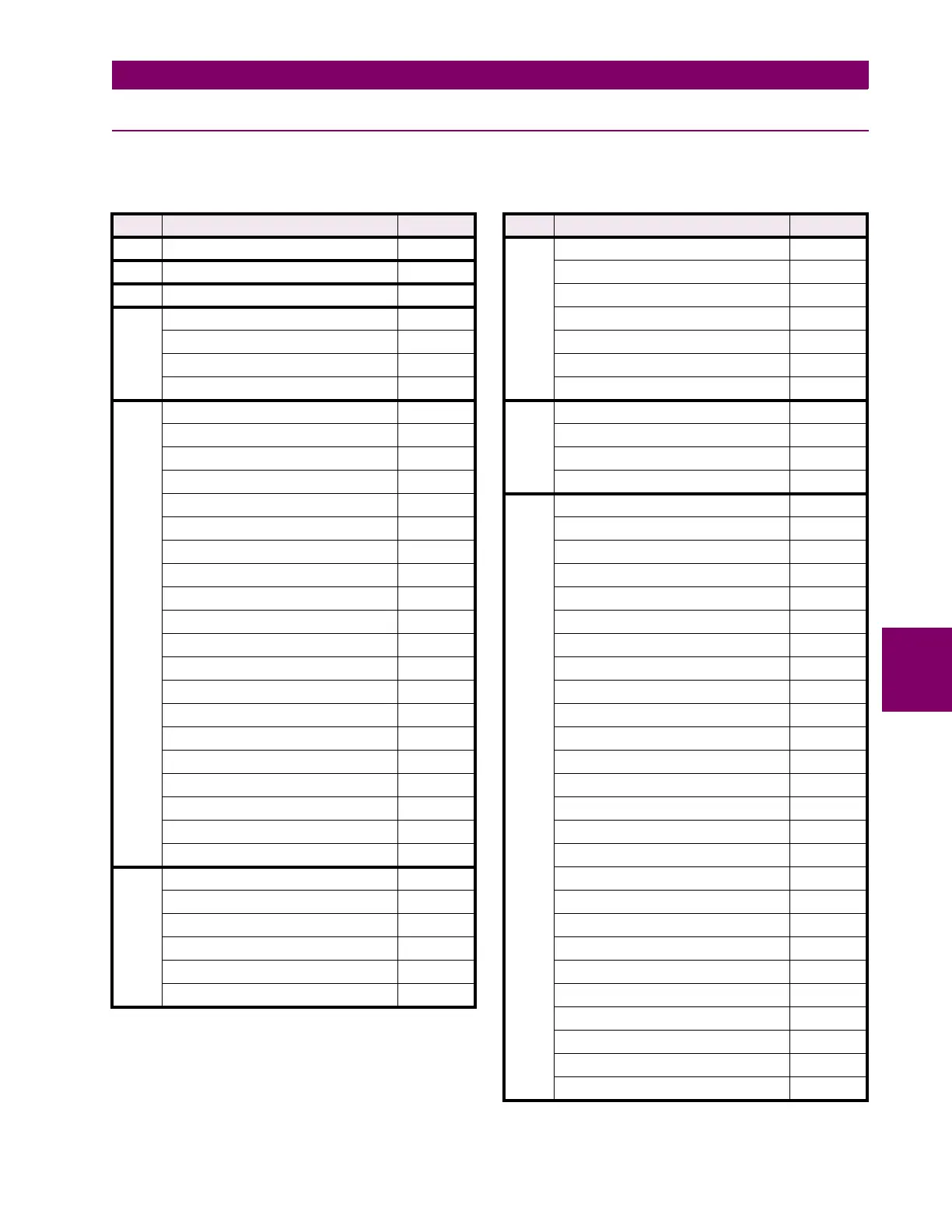
Table 6–13: DATA FORMATS (Sheet 1 of 15)
CODE DESCRIPTION BITMASK
F1 Unsigned Integer: Numerical Data FFFF
F2 Unsigned Long Int: Numerical Data FFFFFFFF
F3 Signed Long Integer: Numerical Data FFFFFFFF
F4 Hardware Version Code ---
1 = A ---
↓↓
26 = Z ---
F5 Unsigned Integer: Cause of Stop FFFF
0 = No Stop ---
1 = Process Interlock A Stop ---
2 = Process Interlock B Stop ---
3 = Process Interlock C Stop ---
4 = Process Interlock D Stop ---
5 = External Stop ---
6 = ESD Stop ---
7 = Process Interlock E Stop ---
8 = Process Interlock F Stop ---
9 = Process Interlock G Stop ---
10 = Process Interlock H Stop ---
11 = Process Interlock I Stop ---
12 = Process Interlock J Stop ---
13 = Faceplate Stop ---
14 = Process Stop ---
15 = Serial Stop ---
16 = Two-Wire Stop ---
17 = Stop A Interlock Stop ---
18 = Stop B Interlock Stop ---
F6 Unsigned Integer: Command Mode FFFF
0 = Manual ---
1 = Auto ---
2 = Manual Inhibit ---
3 = Manual and Auto ---
4 = Hard-Wire Auto ---
F7 Unsigned Integer - Drive Status FFFF
0 = Unavailable ---
1 = Available - Auto ---
2 = Available - Manual ---
3 = Available (Manual & Auto) ---
4 = Running ---
5 = ESD TRIP or STOP (Mod)
F8 Unsigned Integer: Motor Mode FFFF
0 = Starting ---
1 = Stopped ---
2 = Running ---
F9 Unsigned Integer - Cause of Trip FFFF
0 = No Trip ---
1 = Process Interlock A ---
2 = Process Interlock B ---
3 = Process Interlock C ---
4 = Process Interlock D ---
5 = Parameters Not Set ---
6 = Faceplate Stop ---
7 = Process Stop ---
11 = Overload ---
12 = Single Phase ---
13 = Thermistor ---
14 = Acceleration Time ---
15 = Ground Fault ---
16 = Stalled Rotor ---
17 = Not Used ---
18 = Local Isolator ---
19 = Serial Communications Failure ---
20 = Internal Fault ---
21 = Undercurrent ---
22 = Emergency Stop ---
23 = Underpower ---
24 = Analog Input High ---
25 = Analog Input Low ---
26 = Plant Interlock ---
27 = Process Interlock E ---
Table 6–13: DATA FORMATS (Sheet 2 of 15)
CODE DESCRIPTION BITMASK

 Loading...


