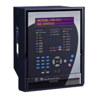
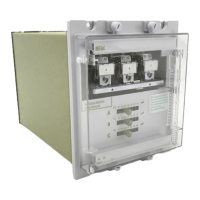
Application example
34 750/760 Quick Reference Guide
– any additional intentional time delay
– directionality (if applicable)
• Define how many output contacts will be energized in response to a given protection
function. Note that the 750/760 relay can be programmed to trip and, at the same
time, to energize one, a combination, or all five auxiliary relays during the process.
• Define if the output relays will be set as fail-safe type.
• Define if the 750/760 will be used to close the breaker. If that will be the case, gather
information on the conditions that will be used to verify synchronism.
• Define if the relay will be used to monitor the status of the breaker. It is strongly
recommended that the 750/760 always be programmed to monitor breaker status by
means of a digital input connected to the one of the 750/760 logic inputs. Use an
auxiliary contact from the breaker either a normally open contact, 52a, which is
normally in open position when the breaker is open, or a normally closed contact, 52b,
which is in closed position when the breaker is open. A combination of both can also
be utilized, adding the capability for monitoring pole discrepancy, an indication of a
potential mechanical problem within the main contact mechanism of the breaker.
• If the relay will be used to respond to logic inputs, prepare a list including:
– logic input name
– condition by which the logic input would be considered asserted
– function that the logic input will initiate within the 750/760.
• If the relay will be used to perform monitoring functions and act upon certain
conditions, gather information such as:
– minimum and maximum values
– alarm and trip values
– time delays
– demand method to be used
– breaker timings
• It is important to familiarize yourself with the relay control functions before setting up
the relay. Some control functions such as the Transfer scheme, which takes automatic
control of the auxiliary outputs, or the autorecloser that uses the auxiliary outputs for
specific pre-defined functions, can have an unwanted effects in the performance of
other functions within the relay.
To start, simply power on the unit, and follow the instructions in this tutorial. The example
assumes the following system characteristics. It also assumes that relay setpoints are
unaltered from their factory default values.
Refer to the following figures for schematics related to this application example.

 Loading...


