CHAPTER 5: MONITORING A3 POWER ANALYSIS
PQM POWER QUALITY METER – INSTRUCTION MANUAL 5–27
stored as WYE. Line to line voltages will appear when the setpoint
S2 SYSTEM SETUP \ CURRENT/VOLTAGE CONFIGURATION \ VT WIRING is stored as
DELTA.
Ia/Ib/Ic/In MAX THD: The maximum total harmonic value for each current input and the
time and date which the maximum value occurred are displayed. The
S1PQMSETUP\CLEARDATA\CLEARMAXTHDVALUES setpoint clears this value.
Van/Vbn/Vcn/Vab/Vbc MAX THD: These messages display the maximum total harmonic
value for each voltage input and the time and date at which the maximum value occurred.
The setpoint
S1PQMSETUP\CLEAR DATA\CLEARMAXTHDVALUES is used to clear
this value. Phase to neutral voltages will appear when the setpoint
S2 SYSTEM SETUP \ CURRENT/VOLTAGE CONFIGURATION \ VT WIRING is set to WYE.
Line to line voltages will appear when the setpoint
S2 SYSTEM SETUP \ CURRENT/
VOLTAGE CONFIGURATION \ VT WIRING
is set to DELTA.
5.4.3 Data Logger
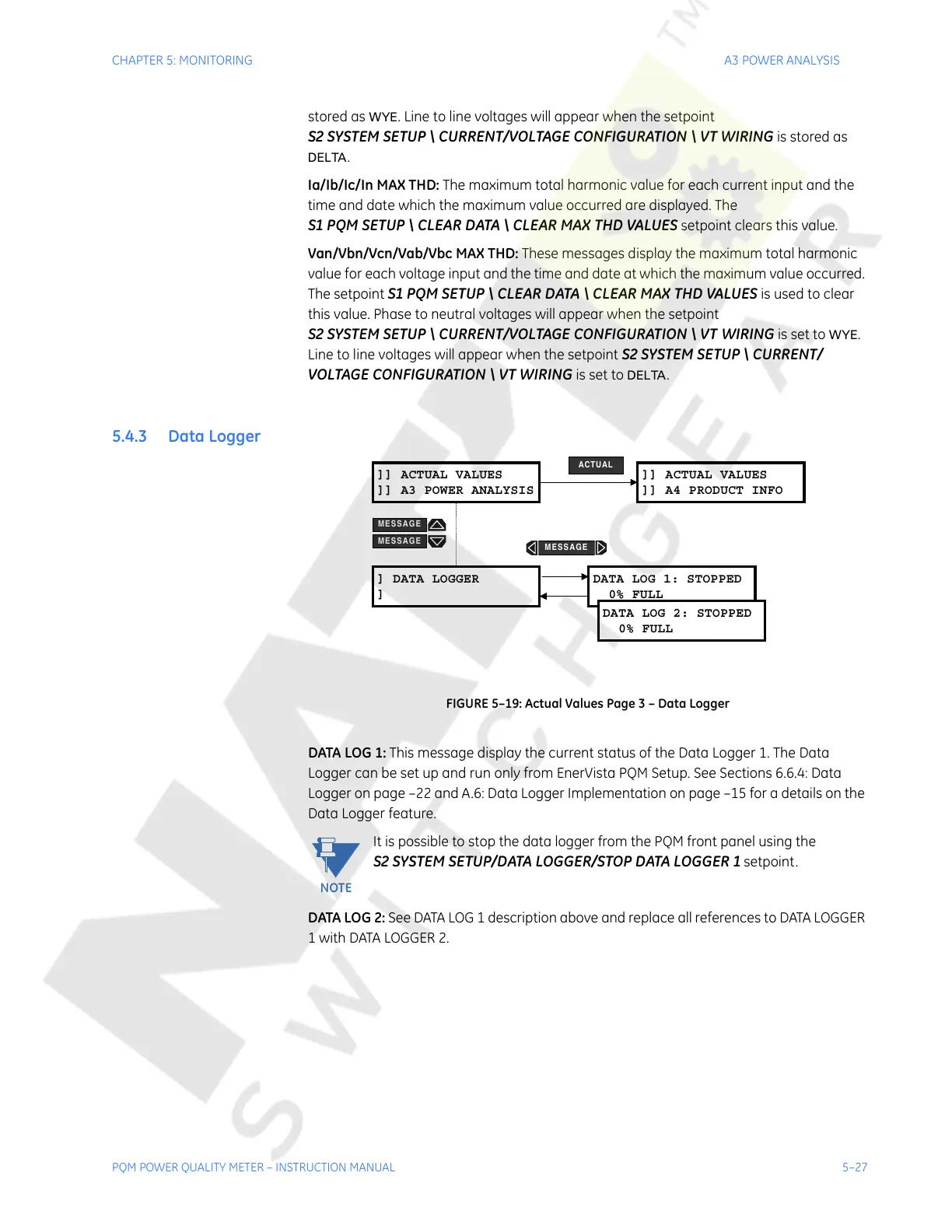
FIGURE 5–19: Actual Values Page 3 – Data Logger
DATA LOG 1: This message display the current status of the Data Logger 1. The Data
Logger can be set up and run only from EnerVista PQM Setup. See Sections 6.6.4: Data
Logger on page –22 and A.6: Data Logger Implementation on page –15 for a details on the
Data Logger feature.
It is possible to stop the data logger from the PQM front panel using the
S2 SYSTEM SETUP/DATA LOGGER/STOP DATA LOGGER 1 setpoint.
DATA LOG 2: See DATA LOG 1 description above and replace all references to DATA LOGGER
1 with DATA LOGGER 2.
]] ACTUAL VALUES
]] A3 POWER ANALYSIS
] DATA LOGGER
]
DATA LOG 1: STOPPED
0% FULL
DATA LOG 2: STOPPED
0% FULL
]] ACTUAL VALUES
]] A4 PRODUCT INFO
ACTUAL
MESSAGE
MESSAGE
MESSAGE
NOTE
Courtesy of NationalSwitchgear.com