4–18 PQM POWER QUALITY METER – INSTRUCTION MANUAL
S1 PQM SETUP CHAPTER 4: PROGRAMMING
data on all inputs are captured in the buffer on a switch D open transition. The number
of cycles captured depends on the value specified in the
TRACE MEMORY USAGE
setpoint.
• TRACE MEMORY TRIGGER DELAY: In some applications it may be necessary to delay
the trigger point to observe the data before the fault occurred. The PQM allows the
trigger to be delayed by the amount of cycles set in this setpoint. Therefore, buffer will
always contain the number cycles specified in this setpoint before the trigger point
and the remaining space in the buffer is filled with the cycles after the trigger point.
• TRACE MEMORY TRIGGER RELAY: The relay selected here will be activated upon the
occurrence of a Trace Memory Trigger. This relay will be cleared once the Trace
Memory is re-armed.
See the application note in Section A.4: Triggered Trace Memory for additional details.
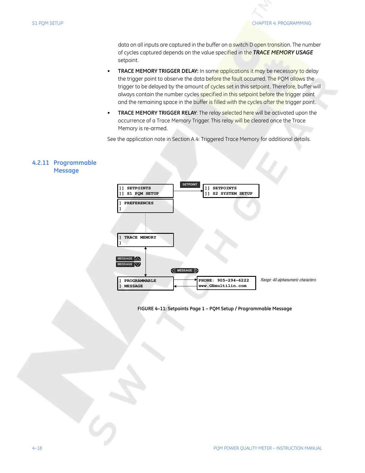
4.2.11 Programmable
Message
FIGURE 4–11: Setpoints Page 1 – PQM Setup / Programmable Message
]] SETPOINTS
]] S1 PQM SETUP
PHONE: 905-294-6222
www.GEmultilin.com
]] SETPOINTS
]] S2 SYSTEM SETUP
SETPOINT
] PREFERENCES
]
Range: 40 alphanumeric characters
] PROGRAMMABLE
] MESSAGE
] TRACE MEMORY
]
MESSAGE
MESSAGE
MESSAGE
Courtesy of NationalSwitchgear.com