CHAPTER 8: DNP COMMUNICATIONS DNP 3.0 PROTOCOL
PQM POWER QUALITY METER – INSTRUCTION MANUAL 8–9
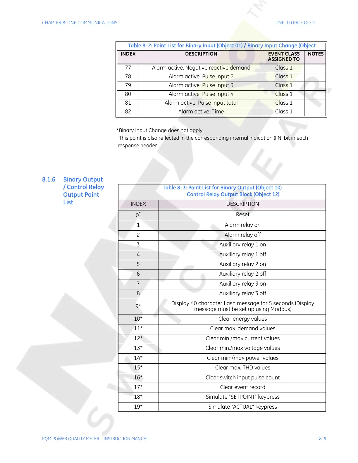
8.1.6 Binary Output
/ Control Relay
Output Point
List
77 Alarm active: Negative reactive demand Class 1
78 Alarm active: Pulse input 2 Class 1
79 Alarm active: Pulse input 3 Class 1
80 Alarm active: Pulse input 4 Class 1
81 Alarm active: Pulse input total Class 1
82 Alarm active: Time Class 1
*Binary Input Change does not apply.
This point is also reflected in the corresponding internal indication (IIN) bit in each
response header.
Table 8–2: Point List for Binary Input (Object 01) / Binary Input Change (Object
INDEX DESCRIPTION EVENT CLASS
ASSIGNED TO
NOTES
Table 8–3: Point List for Binary Output (Object 10)
Control Relay Output Block (Object 12)
INDEX DESCRIPTION
0
*
Reset
1 Alarm relay on
2Alarm relay off
3 Auxiliary relay 1 on
4 Auxiliary relay 1 off
5 Auxiliary relay 2 on
6 Auxiliary relay 2 off
7 Auxiliary relay 3 on
8 Auxiliary relay 3 off
9*
Display 40 character flash message for 5 seconds (Display
message must be set up using Modbus)
10* Clear energy values
11* Clear max. demand values
12* Clear min./max current values
13* Clear min./max voltage values
14* Clear min./max power values
15* Clear max. THD values
16* Clear switch input pulse count
17* Clear event record
18* Simulate “SETPOINT” keypress
19* Simulate “ACTUAL” keypress
Courtesy of NationalSwitchgear.com