CHAPTER 7: MODBUS COMMUNICATIONS MODBUS MEMORY MAP
PQM POWER QUALITY METER – INSTRUCTION MANUAL 7–17
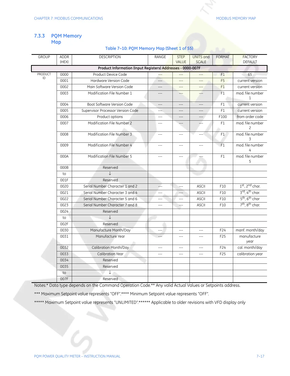
7.3.3 PQM Memory
Map
Table 7–10: PQM Memory Map (Sheet 1 of 55)
GROUP ADDR
(HEX)
DESCRIPTION RANGE STEP
VALUE
UNITS and
SCALE
FORMAT FACTORY
DEFAULT
Product Information (Input Registers) Addresses - 0000-007F
PRODUCT
ID
0000 Product Device Code --- --- --- F1 65
0001 Hardware Version Code --- --- --- F5 current version
0002 Main Software Version Code --- --- --- F1 current version
0003 Modification File Number 1 --- --- --- F1 mod. file number
1
0004 Boot Software Version Code --- --- --- F1 current version
0005 Supervisor Processor Version Code --- --- --- F1 current version
0006 Product options --- --- --- F100 from order code
0007 Modification File Number 2 --- --- --- F1 mod. file number
2
0008 Modification File Number 3 --- --- --- F1 mod. file number
3
0009 Modification File Number 4 --- --- --- F1 mod. file number
4
000A Modification File Number 5 --- --- --- F1 mod. file number
5
000B Reserved
to ↓
001F Reserved
0020 Serial Number Character 1 and 2 --- --- ASCII F10 1
st
, 2
nd
char.
0021 Serial Number Character 3 and 4 --- --- ASCII F10 3
rd
, 4
th
char.
0022 Serial Number Character 5 and 6 --- --- ASCII F10 5
th
, 6
th
char
0023 Serial Number Character 7 and 8 --- --- ASCII F10 7
th
, 8
th
char.
0024 Reserved
to ↓
002F Reserved
0030 Manufacture Month/Day --- --- --- F24 manf. month/day
0031 Manufacture Year --- --- --- F25 manufacture
year
0032 Calibration Month/Day --- --- --- F24 cal. month/day
0033 Calibration Year --- --- --- F25 calibration year
0034 Reserved
0035 Reserved
to ↓
007F Reserved
Notes:* Data type depends on the Command Operation Code.** Any valid Actual Values or Setpoints address.
*** Maximum Setpoint value represents “OFF”.**** Minimum Setpoint value represents “OFF”.
***** Maximum Setpoint value represents “UNLIMITED”.****** Applicable to older revisions with VFD display only
Courtesy of NationalSwitchgear.com