CHAPTER 4: PROGRAMMING S2 SYSTEM SETUP
PQM POWER QUALITY METER – INSTRUCTION MANUAL 4–21
4.3 S2 System Setup
4.3.1 Current/
Voltage
Configuration
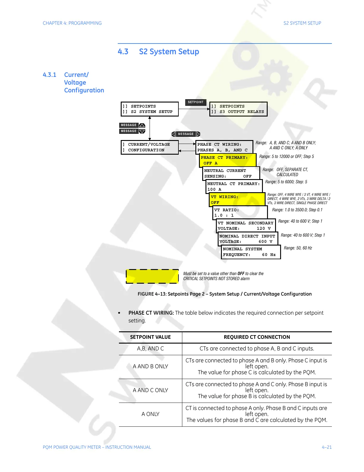
FIGURE 4–13: Setpoints Page 2 – System Setup / Current/Voltage Configuration
• PHASE CT WIRING: The table below indicates the required connection per setpoint
setting.
]] SETPOINTS
]] S2 SYSTEM SETUP
] CURRENT/VOLTAGE
] CONFIGURATION
PHASE CT WIRING:
PHASES A, B, AND C
PHASE CT PRIMARY:
OFF A
NEUTRAL CURRENT
SENSING: OFF
]] SETPOINTS
]] S3 OUTPUT RELAYS
SETPOINT
Range: A, B, AND C; A AND B ONLY;
A AND C ONLY; A ONLY
Range: 5 to 12000 or OFF; Step 5
Range: OFF, SEPARATE CT,
CALCULATED
NEUTRAL CT PRIMARY:
100 A
VT WIRING:
OFF
VT RATIO:
1.0:1
VT NOMINAL SECONDARY
VOLTAGE: 120 V
NOMINAL DIRECT INPUT
VOLTAGE: 600 V
Range: 5 to 6000; Step: 5
NOMINAL SYSTEM
FREQUENCY: 60 Hz
Range: OFF, 4 WIRE WYE / 3 VT, 4 WIRE WYE /
DIRECT, 4 WIRE WYE, 2 VTs, 3 WIRE DELTA / 2
VTs, 3 WIRE DIRECT, SINGLE PHASE DIRECT
Range: 1.0 to 3500.0; Step 0.1
Range: 40 to 600 V; Step 1
Range: 40 to 600 V; Step 1
Range: 50, 60 Hz
MESSAGE
MESSAGE
MESSAGE
Must be set to a value other than
OFF
to clear the
CRITICAL SETPOINTS NOT STORED alarm
SETPOINT VALUE REQUIRED CT CONNECTION
A,B, AND C CTs are connected to phase A, B and C inputs.
A AND B ONLY
CTs are connected to phase A and B only. Phase C input is
left open.
The value for phase C is calculated by the PQM.
A AND C ONLY
CTs are connected to phase A and C only. Phase B input is
left open.
The value for phase B is calculated by the PQM.
A ONLY
CT is connected to phase A only. Phase B and C inputs are
left open.
The values for phase B and C are calculated by the PQM.
Courtesy of NationalSwitchgear.com