CHAPTER 8: DNP COMMUNICATIONS DNP 3.0 PROTOCOL
PQM POWER QUALITY METER – INSTRUCTION MANUAL 8–7
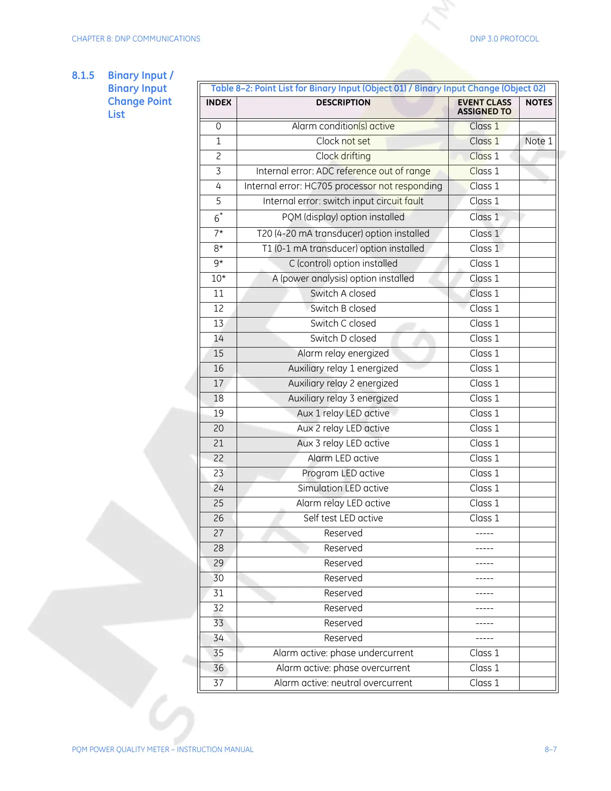
8.1.5 Binary Input /
Binary Input
Change Point
List
Table 8–2: Point List for Binary Input (Object 01) / Binary Input Change (Object 02)
INDEX DESCRIPTION EVENT CLASS
ASSIGNED TO
NOTES
0 Alarm condition(s) active Class 1
1 Clock not set Class 1 Note 1
2 Clock drifting Class 1
3 Internal error: ADC reference out of range Class 1
4 Internal error: HC705 processor not responding Class 1
5 Internal error: switch input circuit fault Class 1
6
*
PQM (display) option installed Class 1
7* T20 (4-20 mA transducer) option installed Class 1
8* T1 (0-1 mA transducer) option installed Class 1
9* C (control) option installed Class 1
10* A (power analysis) option installed Class 1
11 Switch A closed Class 1
12 Switch B closed Class 1
13 Switch C closed Class 1
14 Switch D closed Class 1
15 Alarm relay energized Class 1
16 Auxiliary relay 1 energized Class 1
17 Auxiliary relay 2 energized Class 1
18 Auxiliary relay 3 energized Class 1
19 Aux 1 relay LED active Class 1
20 Aux 2 relay LED active Class 1
21 Aux 3 relay LED active Class 1
22 Alarm LED active Class 1
23 Program LED active Class 1
24 Simulation LED active Class 1
25 Alarm relay LED active Class 1
26 Self test LED active Class 1
27 Reserved -----
28 Reserved -----
29 Reserved -----
30 Reserved -----
31 Reserved -----
32 Reserved -----
33 Reserved -----
34 Reserved -----
35 Alarm active: phase undercurrent Class 1
36 Alarm active: phase overcurrent Class 1
37 Alarm active: neutral overcurrent Class 1
Courtesy of NationalSwitchgear.com