7–66 PQM POWER QUALITY METER – INSTRUCTION MANUAL
MODBUS MEMORY MAP CHAPTER 7: MODBUS COMMUNICATIONS
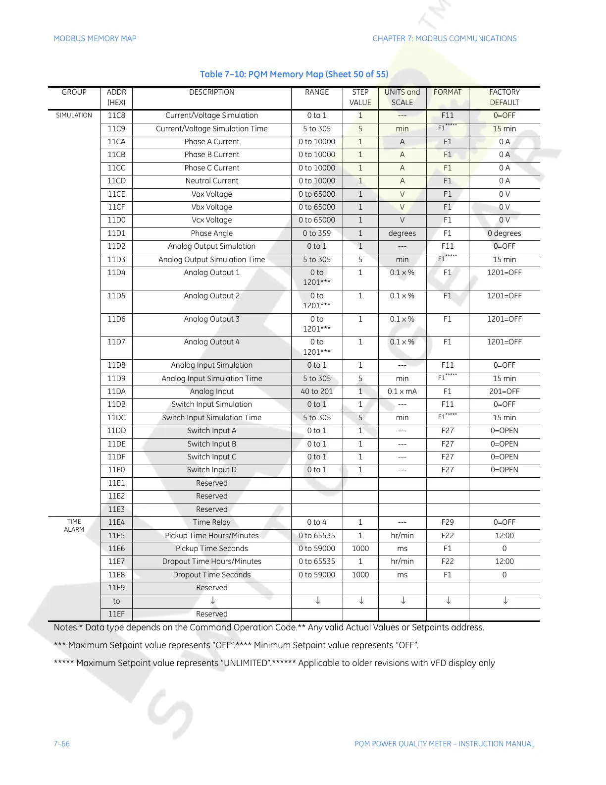
SIMULATION
11C8 Current/Voltage Simulation 0 to 1 1 --- F11 0=OFF
11C9 Current/Voltage Simulation Time 5 to 305 5 min
F1
*****
15 min
11CA Phase A Current 0 to 10000 1 A F1 0 A
11CB Phase B Current 0 to 10000 1 A F1 0 A
11CC Phase C Current 0 to 10000 1 A F1 0 A
11CD Neutral Current 0 to 10000 1 A F1 0 A
11CE Vax Voltage 0 to 65000 1 V F1 0 V
11CF Vbx Voltage 0 to 65000 1 V F1 0 V
11D0 Vcx Voltage 0 to 65000 1 V F1 0 V
11D1 Phase Angle 0 to 359 1 degrees F1 0 degrees
11D2 Analog Output Simulation 0 to 1 1 --- F11 0=OFF
11D3 Analog Output Simulation Time 5 to 305 5 min
F1
*****
15 min
11D4 Analog Output 1 0 to
1201***
1 0.1 x % F1 1201=OFF
11D5 Analog Output 2 0 to
1201***
1 0.1 x % F1 1201=OFF
11D6 Analog Output 3 0 to
1201***
1 0.1 x % F1 1201=OFF
11D7 Analog Output 4 0 to
1201***
1 0.1 x % F1 1201=OFF
11D8 Analog Input Simulation 0 to 1 1 --- F11 0=OFF
11D9 Analog Input Simulation Time 5 to 305 5 min
F1
*****
15 min
11DA Analog Input 40 to 201 1 0.1 x mA F1 201=OFF
11DB Switch Input Simulation 0 to 1 1 --- F11 0=OFF
11DC Switch Input Simulation Time 5 to 305 5 min
F1
*****
15 min
11DD Switch Input A 0 to 1 1 --- F27 0=OPEN
11DE Switch Input B 0 to 1 1 --- F27 0=OPEN
11DF Switch Input C 0 to 1 1 --- F27 0=OPEN
11E0 Switch Input D 0 to 1 1 --- F27 0=OPEN
11E1 Reserved
11E2 Reserved
11E3 Reserved
TIME
ALARM
11E4 Time Relay 0 to 4 1 --- F29 0=OFF
11E5 Pickup Time Hours/Minutes 0 to 65535 1 hr/min F22 12:00
11E6 Pickup Time Seconds 0 to 59000 1000 ms F1 0
11E7 Dropout Time Hours/Minutes 0 to 65535 1 hr/min F22 12:00
11E8 Dropout Time Seconds 0 to 59000 1000 ms F1 0
11E9 Reserved
to ↓ ↓ ↓ ↓ ↓ ↓
11EF Reserved
Table 7–10: PQM Memory Map (Sheet 50 of 55)
GROUP ADDR
(HEX)
DESCRIPTION RANGE STEP
VALUE
UNITS and
SCALE
FORMAT FACTORY
DEFAULT
Notes:* Data type depends on the Command Operation Code.** Any valid Actual Values or Setpoints address.
*** Maximum Setpoint value represents “OFF”.**** Minimum Setpoint value represents “OFF”.
***** Maximum Setpoint value represents “UNLIMITED”.****** Applicable to older revisions with VFD display only
Courtesy of NationalSwitchgear.com