CHAPTER 7: MODBUS COMMUNICATIONS MODBUS MEMORY MAP
PQM POWER QUALITY METER – INSTRUCTION MANUAL 7–73
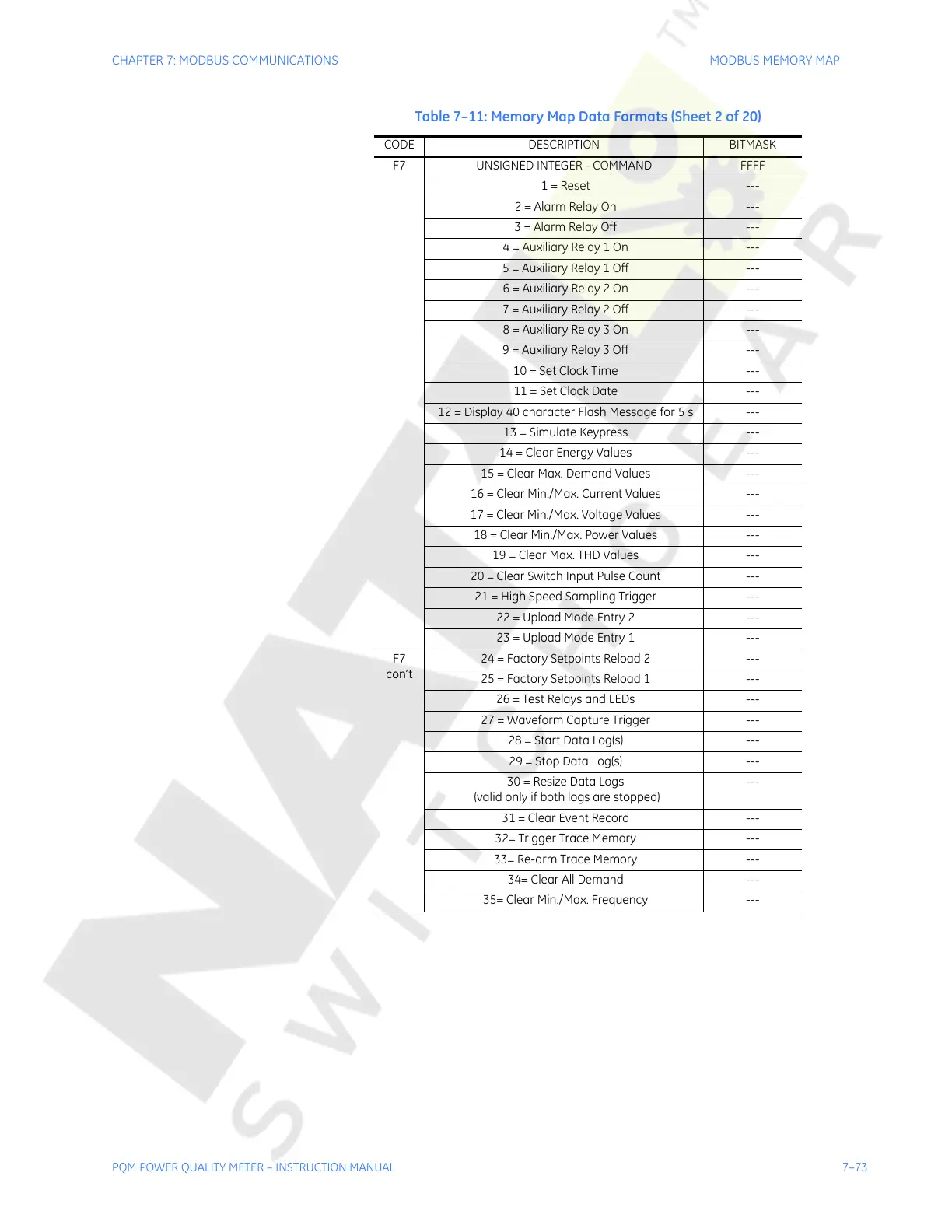
F7 UNSIGNED INTEGER - COMMAND FFFF
1 = Reset ---
2 = Alarm Relay On ---
3 = Alarm Relay Off ---
4 = Auxiliary Relay 1 On ---
5 = Auxiliary Relay 1 Off ---
6 = Auxiliary Relay 2 On ---
7 = Auxiliary Relay 2 Off ---
8 = Auxiliary Relay 3 On ---
9 = Auxiliary Relay 3 Off ---
10 = Set Clock Time ---
11 = Set Clock Date ---
12 = Display 40 character Flash Message for 5 s ---
13 = Simulate Keypress ---
14 = Clear Energy Values ---
15 = Clear Max. Demand Values ---
16 = Clear Min./Max. Current Values ---
17 = Clear Min./Max. Voltage Values ---
18 = Clear Min./Max. Power Values ---
19 = Clear Max. THD Values ---
20 = Clear Switch Input Pulse Count ---
21 = High Speed Sampling Trigger ---
22 = Upload Mode Entry 2 ---
23 = Upload Mode Entry 1 ---
F7
con’t
24 = Factory Setpoints Reload 2 ---
25 = Factory Setpoints Reload 1 ---
26 = Test Relays and LEDs ---
27 = Waveform Capture Trigger ---
28 = Start Data Log(s) ---
29 = Stop Data Log(s) ---
30 = Resize Data Logs
(valid only if both logs are stopped)
---
31 = Clear Event Record ---
32= Trigger Trace Memory ---
33= Re-arm Trace Memory ---
34= Clear All Demand ---
35= Clear Min./Max. Frequency ---
Table 7–11: Memory Map Data Formats (Sheet 2 of 20)
CODE DESCRIPTION BITMASK
Courtesy of NationalSwitchgear.com