7–86 PQM POWER QUALITY METER – INSTRUCTION MANUAL
MODBUS MEMORY MAP CHAPTER 7: MODBUS COMMUNICATIONS
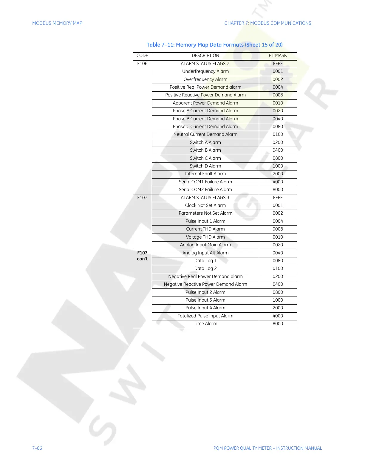
F106 ALARM STATUS FLAGS 2: FFFF
Underfrequency Alarm 0001
Overfrequency Alarm 0002
Positive Real Power Demand alarm 0004
Positive Reactive Power Demand Alarm 0008
Apparent Power Demand Alarm 0010
Phase A Current Demand Alarm 0020
Phase B Current Demand Alarm 0040
Phase C Current Demand Alarm 0080
Neutral Current Demand Alarm 0100
Switch A Alarm 0200
Switch B Alarm 0400
Switch C Alarm 0800
Switch D Alarm 1000
Internal Fault Alarm 2000
Serial COM1 Failure Alarm 4000
Serial COM2 Failure Alarm 8000
F107 ALARM STATUS FLAGS 3: FFFF
Clock Not Set Alarm 0001
Parameters Not Set Alarm 0002
Pulse Input 1 Alarm 0004
Current THD Alarm 0008
Voltage THD Alarm 0010
Analog Input Main Alarm 0020
F107
con’t
Analog Input Alt Alarm 0040
Data Log 1 0080
Data Log 2 0100
Negative Real Power Demand alarm 0200
Negative Reactive Power Demand Alarm 0400
Pulse Input 2 Alarm 0800
Pulse Input 3 Alarm 1000
Pulse Input 4 Alarm 2000
Totalized Pulse Input Alarm 4000
Time Alarm 8000
Table 7–11: Memory Map Data Formats (Sheet 15 of 20)
CODE DESCRIPTION BITMASK
Courtesy of NationalSwitchgear.com

 Loading...


