4–8 PQM POWER QUALITY METER – INSTRUCTION MANUAL
S1 PQM SETUP CHAPTER 4: PROGRAMMING
4.2.5 DNP 3.0
Configuration
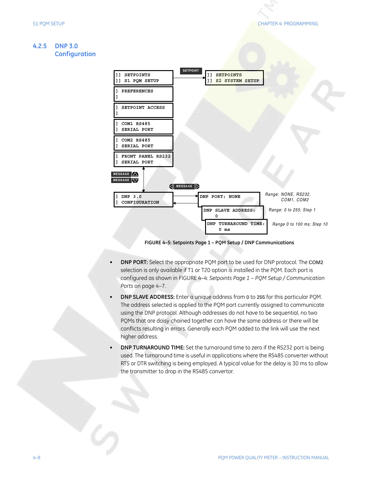
FIGURE 4–5: Setpoints Page 1 – PQM Setup / DNP Communications
• DNP PORT: Select the appropriate PQM port to be used for DNP protocol. The COM2
selection is only available if T1 or T20 option is installed in the PQM. Each port is
configured as shown in FIGURE 4–4: Setpoints Page 1 – PQM Setup / Communication
Ports on page 4–7.
• DNP SLAVE ADDRESS: Enter a unique address from
0 to 255 for this particular PQM.
The address selected is applied to the PQM port currently assigned to communicate
using the DNP protocol. Although addresses do not have to be sequential, no two
PQMs that are daisy chained together can have the same address or there will be
conflicts resulting in errors. Generally each PQM added to the link will use the next
higher address.
• DNP TURNAROUND TIME: Set the turnaround time to zero if the RS232 port is being
used. The turnaround time is useful in applications where the RS485 converter without
RTS or DTR switching is being employed. A typical value for the delay is 30 ms to allow
the transmitter to drop in the RS485 convertor.
]] SETPOINTS
]] S1 PQM SETUP
] DNP 3.0
] CONFIGURATION
DNP PORT: NONE
DNP SLAVE ADDRESS:
0
DNP TURNAROUND TIME:
0ms
]] SETPOINTS
]] S2 SYSTEM SETUP
SETPOINT
Range: NONE, RS232,
COM1, COM2
Range 0 to 100 ms; Step 10
Range: 0 to 255; Step 1
] PREFERENCES
]
] SETPOINT ACCESS
]
] COM2 RS485
] SERIAL PORT
] COM1 RS485
] SERIAL PORT
] FRONT PANEL RS232
] SERIAL PORT
MESSAGE
MESSAGE
MESSAGE
Courtesy of NationalSwitchgear.com