GE COMPANY
D
IRECTION 5745295-1EN, REVISION 1 OPTIMA CT520 DOD IB UPGRADE INSTRUCTION
Chapter 2 - Upgrade Procedure Page 31
c.) Connect the LCD Monitor power cables to NIO16 Console AC Box.
- Scan Monitor
Video Cable: from Console Host DP1 to Monitor DVI
Power Cable: from Console AC Box J10 to Monitor
- Image Monitor
Video Cable: from Console Host DP0 to Monitor DVI
Power Cable: from Console AC Box J9 to Monitor
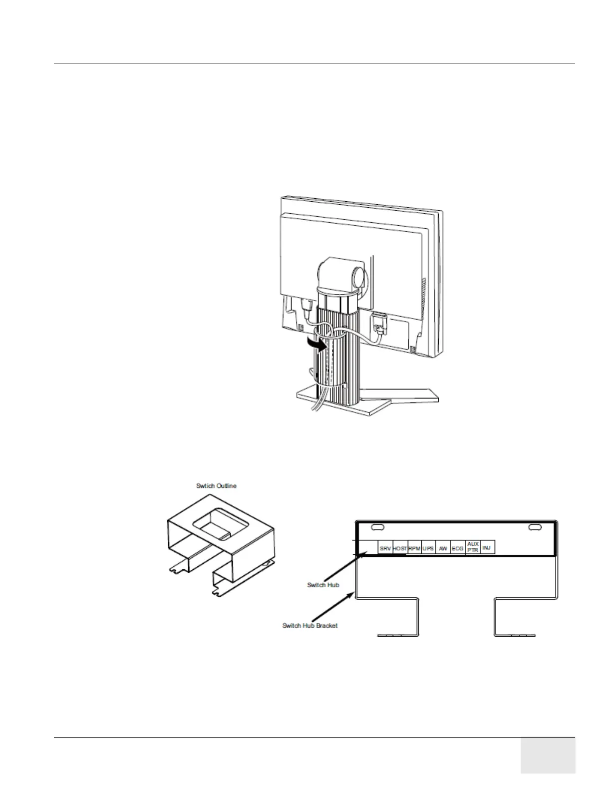
d.) Route LCD video cable and power cable.
Figure 2-11 Cable Routing and Keeper
5.) Plug cables into Switch Hub on console if request.
6.) Connect other cables to Z820 Host Computer according to Figure 2-7.
Figure 2-12 Switch Hub Connections
7.) Connect the NIO16 Console power cable and Ground cable to the Console Power Panel.
2.2.5 Console Cover Installation
Refer to Console Cover Installation procedure in 5350500-2EN rev15 or later service manual.
Note: If customer purchases ASiR option, the Console Covers are black or else they are white.