– 30 –
Inlet Safety Thermostat
On electric models, the inlet safety thermostat is
located on the top left area of the heater housing,
to the left of the inlet control thermistor. On gas
models, the inlet safety thermostat is located on
the right side of the diffuser, above the inlet control
thermistor. The thermostat monitors incoming air
temperature.
If the thermostat reaches a temperature beyond its
maximum temperature rating, it will trip and disable
power to the heating elements (electric models) or
burner assembly (gas models).
On electric dryers, the inlet safety thermostat opens
at 210°F (99°C) and will automatically reset at 180°F
(82°C). On gas dryers, the inlet safety thermostat
opens at 300°F (149°C) and will automatically reset
at 260°F (127°C).
To remove the inlet safety thermostat:
Remove the drum. (See 1. Drum.)
Disconnect the 2 wires from the inlet safety 2.
thermostat.
Remove the Phillips-head screw that attaches 3.
the inlet safety thermostat to the heater
assembly or diffuser.
Lift and slide the thermostat from the heater 4.
assembly or diffuser.
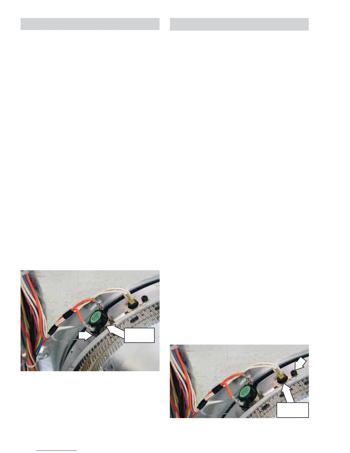
Electric Model Shown
Inlet Control Thermistor
On electric models, the inlet control thermistor is
located on the top left area of the heater housing,
to the right of the inlet safety thermostat. On gas
models, the inlet control thermistor is located on
the right side of the diffuser, below the inlet safety
thermostat. The thermistor monitors incoming
air temperature and relays the information to the
power board.
The thermistor has a negative coeffi cient. As the
temperature increases, the thermistor's resistance
decreases.
Inlet control thermistor approximate resistance
values:
120K • Ω at 69°F (20°C)
100K • Ω at 77°F (25°C)
80K • Ω at 86°F (30°C)
29K • Ω at 130°F (54°C)
19K • Ω at 145°F (63°C)
Operation of the inlet control thermistor can be
checked by using the Inlet Thermistor test in service
test mode. (See
Service Test Mode.)
Specifi c failures associated with the inlet control
thermistor can initiate error codes E2 and E4. (See
Service Test Mode.)
To remove the inlet control thermistor:
Remove the drum. (See 1. Drum.)
Disconnect the 2 wires from the inlet control 2.
thermistor.
Remove the Phillips-head screw that attaches 3.
the inlet control thermistor to the heater
assembly or diffuser.
Lift and slide the thermistor from the heater 4.
assembly or diffuser.
Electric Model Shown
Inlet Control
Thermistor
Inlet Safety
Thermostat
 Loading...