– 33 –
Note: If replacing the power board, transfer the
model selector harness to the replacement power
board in the same location as on the original.
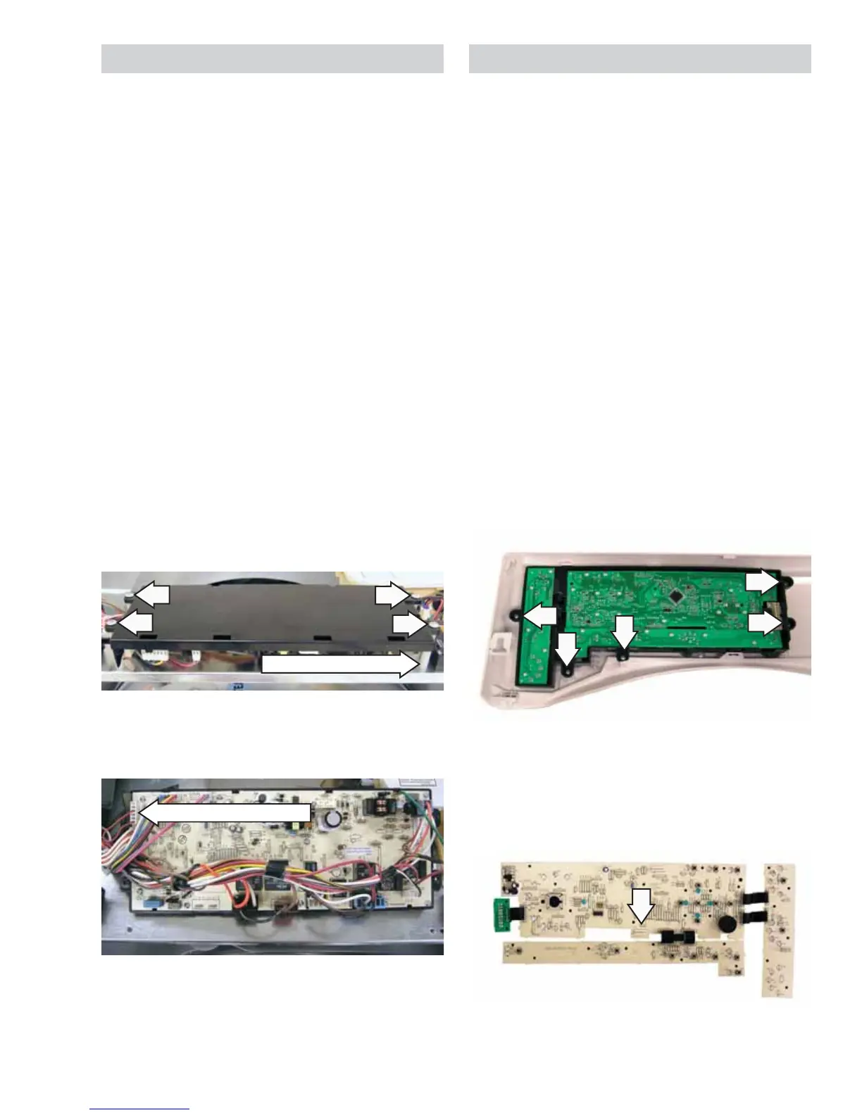
Control Board Assembly
The control board assembly is mounted in a plastic
housing that is attached to the inside of the control
panel. It consists of 3 circuit boards connected by
ribbons. The boards and the plastic housing are
replaced as an assembly.
Operation of the control board assembly can be
checked by using the service test mode. (See Service
Test Mode.)
Error codes that are specifi c to the control board
can initiate error codes E1 and E18. (See Service Test
Mode.)
To remove the control board assembly:
Caution: To avoid marring the control panel, place
the panel face down on a protective surface.
Remove the control and top panels. (See 1. C
ontrol
Panel and Top Panel.)
Remove the 5 Phillips-head screws that attach 2.
the control board plastic housing to the control
panel. Remove the housing.
3. Remove the 26 Phillips-head screws that attach
the control board assembly to the plastic
housing.
4. Remove the wire harness from connection J1.
6. Mark and disconnect the wire harnesses and the
ground wire from the power board assembly.
Power Board
The power board is mounted in a plastic housing
that is attached to a support bracket located
under the top panel. The power board is inverted
(component side facing down), and protected from
moisture damage with a vapor shield.
To remove the power board:
Remove the control and top panels. (See 1.
Control
Panel and Top Panel.)
Separate the steam generator outlet hose at the 2.
coupler.
Remove the Phillips-head screw that attaches 3.
the right side of the vapor shield to the cabinet.
Lift and place the vapor shield over the left side 4.
of the cabinet.
Note: In the following step, a board standoff is
installed under each power board screw. To prevent
a standoff from falling into the dryer, capture each
standoff when removing each power board screw.
5. Remove the 4 Phillips-head screws that attach
the power board to the support bracket.
Board Standoff (1 of 4)
Model Selector Harness
 Loading...