– 26 –
Gas Valve
The burner assembly utilizes a 2-stage gas valve
that ensures better heat control:
First stage – low fl ame – low heat•
Second stage – normal fl ame – high heat•
Control board regulates valve operation for •
proper heat levels
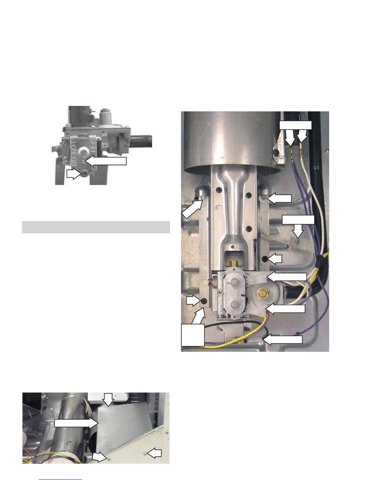
The gas valve is attached to a bracket located in the
bottom, right, front corner of the dryer cabinet.
To remove the gas valve:
Shut off the gas supply to the unit.1.
Disconnect gas supply from the burner inlet pipe.2.
Remove the drum. (See 3. Drum.)
Remove 3 screws and the vapor shield.4.
To remove the half-power coil:
Remove the drum. (See 1.
Drum.)
Disconnect the 2 wires from the half-power coil.2.
Note the position of the locator pin inserted in 3.
the coil bracket.
Remove the Phillips-head screw and the coil 4.
bracket that holds the coil to the valve body.
Note: Upon reassembly, ensure the locator pin is
inserted into the hole provided in the coil bracket.
9. Remove the coils from the gas valve. (See Gas
Valve Coils.)
10. Turn the bracket over. Remove the 3 Phillips-
head screws that attach the gas valve to the
gas valve bracket.
Caution: The ignitor is very fragile. To prevent
breaking the ignitor, care must be taken when
installing the gas valve.
Note: Upon reassembly, ensure the gas valve
bracket
is inserted under the 2 tabs located in
the dryer fl oor.
Disconnect the coil wire harness from each coil 5.
and the 2 wires from the half-power coil.
Disconnect the ignitor wire harness and the 2 6.
wires from the fl ame detector.
Remove the 2 Phillips-head screws that attach 7.
the gas valve bracket to the dryer fl oor.
Pull the bracket toward the front of the dryer to 8.
disengage tabs from dryer fl oor.
Locator Pin
Disconnect
Disconnect
Disconnect
Disconnect
Tab
Tab
Disconnect
Gas
Valve
Bracket
Vapor Shield
 Loading...