– 25 –
Main Coil
Booster Coil
Safety Coil
The half-power coil has an approximate resistance
of 1K Ω.
(Continued Next Page)
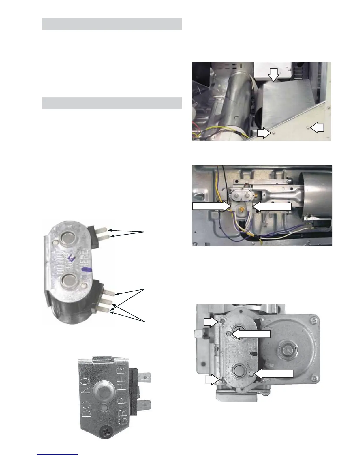
Gas Valve Coils
The burner assembly has a gas valve that utilizes
4 coils. A double coil (safety and booster coils
combined) and a single main coil are located on top
of the gas valve in front of the combustion chamber
opening. A half-power coil is located on the front of
the gas valve. All coils can be replaced separately.
Gas valve coil assembly resistance values:
• Safety coil terminals - 1400 Ω
• Booster coil terminals - 580 Ω
• Main coil terminals - 1300 Ω
To remove the double and main coils:
Remove the drum. (See 1.
Drum.)
Remove 3 screws and the water vapor shield.2.
4. Note the position of the locator pins inserted in
the coil bracket.
5. Remove the 2 Phillips-head screws that attach
the coil bracket to the valve body.
6. Lift the bracket vertically. Lift coils to remove.
Note: Upon reassembly, ensure the locator pins are
inserted into the holes provided in the coil bracket.
Disconnect
Disconnect
Locator Pin
Locator Pin
Burner Assembly and LP Conversion
The burner assembly consists of the gas valve coils,
gas valve, burner, and inlet pipe.
To convert the dryer from natural gas to LP gas,
the burner assembly must be replaced. The burner
cannot be converted to LP gas. Refer to conversion
kit #14-A048.
Disconnect the wire harness from both coils.3.
 Loading...