– 24 –
OUTLET
CONTROL
BACKUP
INLET
SAFETY
L1 L2
RED
GRAY
BLUE BLUE
PURPLE BLACK
DRUM
MOTOR
M1-M2
WHITE
WHITE
STEAM
INTERLOCK
NC
NC
ORANGE
RED ORANGE ORANGE
INNER ELEMENT
19.2 OHMS
OUTER ELEMENT
19.2 OHMS
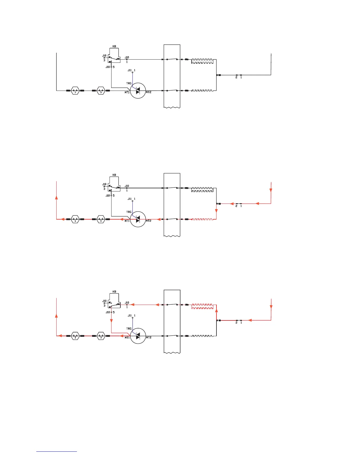
4. As the drum heats up further, relay K8 opens J10 Pin 1 to J10 Pin 5 and cycles off the inner element. The
heat system is now drawing 0 amps.
5. The drum temperature begins to drop and at that time the triac gate voltage, again, begins to pulsate 0
to 4.8 VDC.
6. The outer element is energized and draws approximately 7 amps. This outer element current begins to
climb slowly towards 11 amps.
7. At this point, relay K8 again closes J10 Pin 1 to J10 Pin 5, turns on the inner element, and the triac gate
voltage drops to 0 VDC and the outer element turns off. The inner element again draws approximately 12
amps.
8. This cycling pattern continues throughout the drying period.
OUTLET
CONTROL
BACKUP
INLET
SAFETY
L1 L2
RED
GRAY
BLUE BLUE
PURPLE BLACK
DRUM
MOTOR
M1-M2
WHITE
WHITE
STEAM
INTERLOCK
NC
NC
ORANGE
RED ORANGE ORANGE
INNER ELEMENT
19.2 OHMS
OUTER ELEMENT
19.2 OHMS
OUTLET
CONTROL
BACKUP
INLET
SAFETY
L1 L2
RED
GRAY
BLUE BLUE
PURPLE BLACK
DRUM
MOTOR
M1-M2
WHITE
WHITE
STEAM
INTERLOCK
NC
NC
ORANGE
RED ORANGE ORANGE
INNER ELEMENT
19.2 OHMS
OUTER ELEMENT
19.2 OHMS
 Loading...