– 23 –
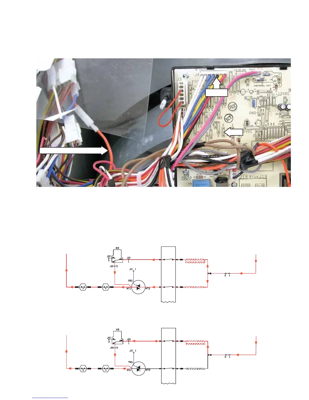
Electric Dryer Element Operation - Normal Heat Cycle
To measure electric heater amperage, locate and read current on the orange wire connecting the inlet •
safety thermostat to MT1 on the triac.
To measure triac gate voltage (VDC), read between J4 Pin 3 (logic ground) and board location JT27.•
The K8 relay closes J10 Pin 1 to J10 Pin 5. This energizes the inner element. At the same time, the triac 1.
is gated with 4.8 VDC. MT1 to MT2 close, turning on the outer element. At this time, both elements are
energized and the heat system is drawing approximately 24 amps.
As the drum temperature begins to rise, the triac gate voltage begins to pulsate between 4.8 and 0 VDC. 2.
The current draw of the outer element begins to drop. The heat system is now drawing somewhere
between 16 and 20 amps.
OUTLET
CONTROL
BACKUP
INLET
SAFETY
L1 L2
RED
GRAY
BLUE BLUE
PURPLE BLACK
DRUM
MOTOR
M1-M2
WHITE
WHITE
STEAM
INTERLOCK
NC
NC
ORANGE
RED ORANGE ORANGE
INNER ELEMENT
19.2 OHMS
OUTER ELEMENT
19.2 OHMS
3. Triac gate voltage fi nally drops to 0 VDC. The outer element is off. The inner element is still operating. The
system is now drawing approximately 12 amps.
OUTLET
CONTROL
BACKUP
INLET
SAFETY
L1 L2
RED
GRAY
BLUE BLUE
PURPLE BLACK
DRUM
MOTOR
M1-M2
WHITE
WHITE
STEAM
INTERLOCK
NC
NC
ORANGE
RED ORANGE ORANGE
INNER ELEMENT
19.2 OHMS
OUTER ELEMENT
19.2 OHMS
Amperage Reading Location
J4 Pin 3
JT27
(Continued Next Page)
 Loading...