– 47 –
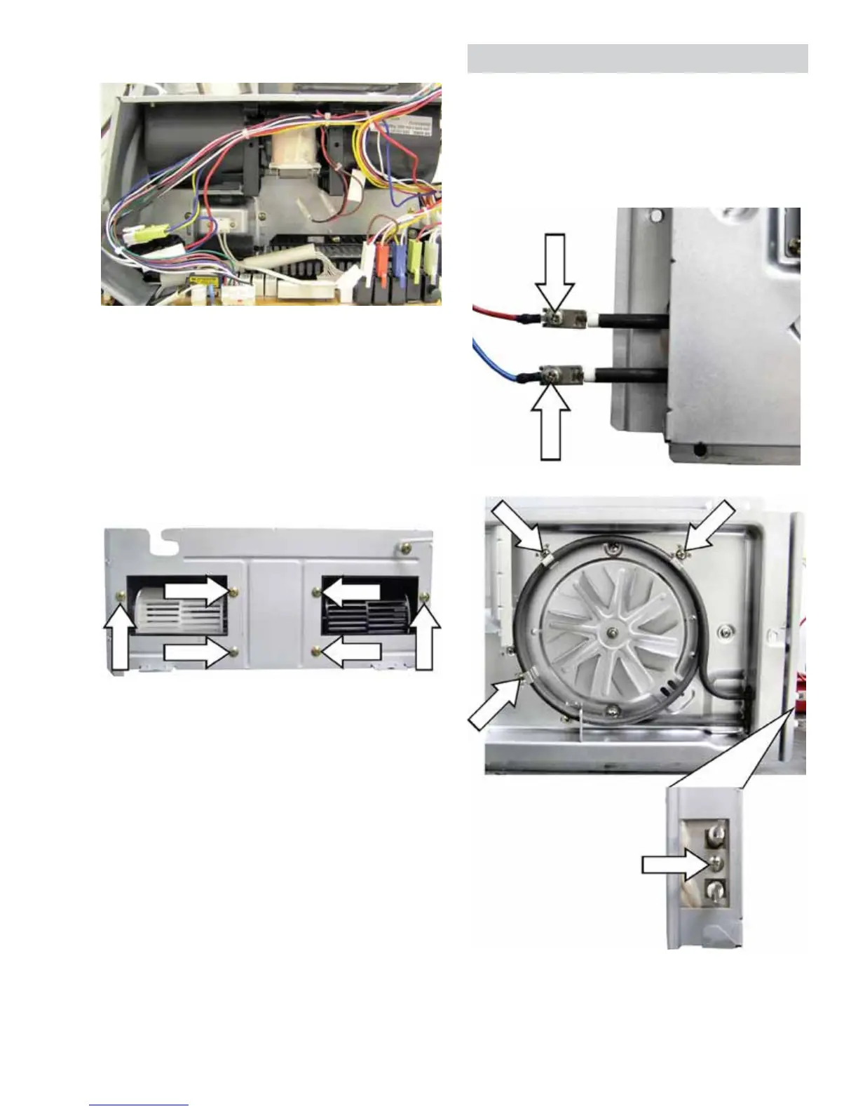
5. Disconnect wire harnesses on the relay board at
locations CN2, RY2. RY7, RY8, RY9, and RY11.
6. Remove the single Phillips head screw that
DWWDFKHVWKH¿OWHUJURXQGZLUHWRWKHRYHQ
chassis.
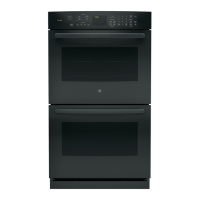
7. 5HPRYHWKH¿YH3KLOOLSVKHDGVFUHZVWKDWDWWDFK
the blower bracket to the oven chassis.
8. Carefully lift the blower assembly from the oven
chassis.
9. Remove the six Phillips head screws that hold
the blower housing to the bracket.
NOTE: When installing the blower assembly, ensure
WKDWWKH¿OWHUJURXQGZLUHLVVHFXUHGWRWKHRYHQ
chassis.
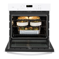
Convection Heater Element
The convection heater assembly is held in place by
two 7 mm hex nuts and 4 Phillips head screws.
The convection heater element has an approximate
UHVLVWDQFHYDOXHRIű7ZR3KLOOLSVKHDGVFUHZV
connect the power wires to the element terminals.
The convection heater
element is held in place
by 4 Phillips head screws.
(Three screws on the
front, and 1 screw on
the end.)
End View of Element