842008A2.CDR
SETTING
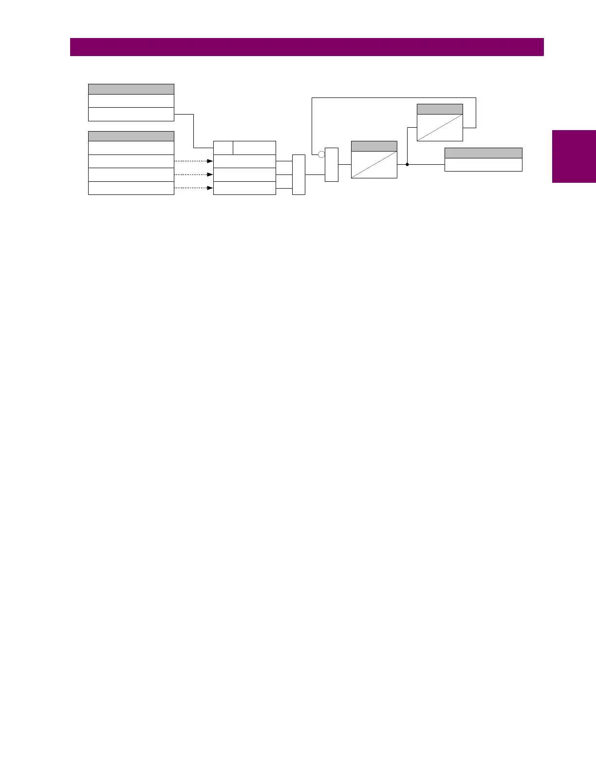
POWER SWING SOURCE:
I_0
I_1
I_2
| |I_0| - |I_0'|| > K_0
SETTING
POWER SWING FUNCTION:
Enabled = 1
| |I_1| - |I_1'|| > K_1
| |I_2| - |I_2'|| > K_2
RUN
OR
I_0, I_1, I_2 - present values
I_0', I_1', I_2' - half-a-cycle old values
K_0, K_2 - three times the average change over last power cycle
K_1 - four times the average change over last power cycle
AND
0
4 cycles
TIMER
0
10 cycles
TIMER
FLEXLOGIC OPERAND
POWER SWING 50DD