GE Multilin T60 Transformer Protection System 5-303
5 SETTINGS 5.7 CONTROL ELEMENTS
5
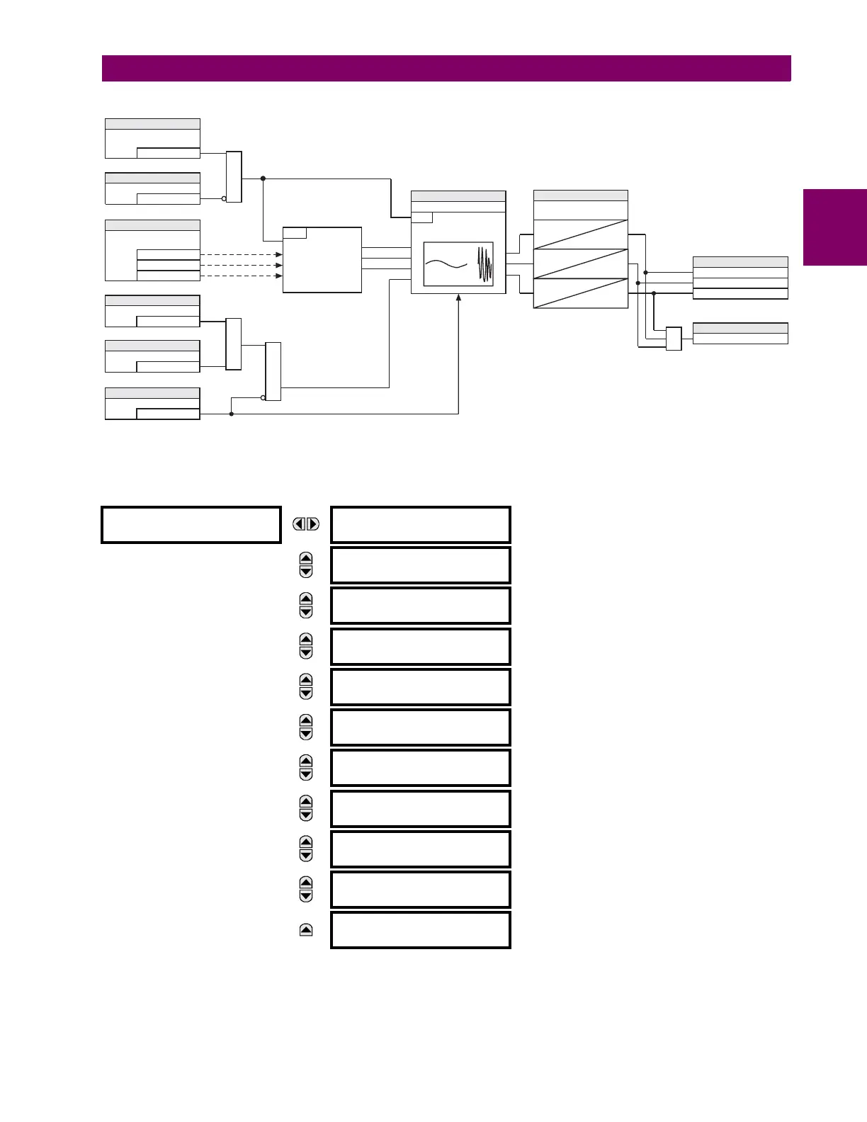
Figure 5–154: BREAKER RESTRIKE SCHEME LOGIC
e) CT FAILURE DETECTOR
PATH: SETTINGS CONTROL ELEMENTS MONITORING ELEMENTS CT FAILURE DETECTOR
The CT failure function is designed to detect problems with system current transformers used to supply current to the relay.
This logic detects the presence of a zero-sequence current at the supervised source of current without a simultaneous
zero-sequence current at another source, zero-sequence voltage, or some protection element condition.
CT FAILURE
DETECTOR
CT FAIL FUNCTION:
Disabled
Range: Disabled, Enabled
MESSAGE
CT FAIL BLOCK:
Off
Range: FlexLogic operand
MESSAGE
CT FAIL 3I0 INPUT 1:
SRC 1
Range: SRC 1, SRC 2, SRC 3, SRC 4
MESSAGE
CT FAIL 3I0 INPUT 1
PKP: 0.2 pu
Range: 0.0 to 2.0 pu in steps of 0.1
MESSAGE
CT FAIL 3I0 INPUT 2:
SRC 2
Range: SRC 1, SRC 2, SRC 3, SRC 4
MESSAGE
CT FAIL 3I0 INPUT 2
PKP: 0.2 pu
Range: 0.0 to 2.0 pu in steps of 0.1
MESSAGE
CT FAIL 3V0 INPUT:
SRC 1
Range: SRC 1, SRC 2, SRC 3, SRC 4
MESSAGE
CT FAIL 3V0 INPUT
PKP: 0.20 pu
Range: 0.00 to 2.00 pu in steps of 0.01
MESSAGE
CT FAIL PICKUP
DELAY: 1.000 s
Range: 0.000 to 65.535 s in steps of 0.001
MESSAGE
CT FAIL TARGET:
Self-reset
Range: Self-reset, Latched, Disabled
MESSAGE
CT FAIL EVENTS:
Disabled
Range: Disabled, Enabled
RUN
Current interruption
detection logic
<0.05pu
for > ¼ cycle
I
t
mag
ARMED
RESET
SETTING
= Enabled
BREAKER RESTRIKE 1
FUNCTION
SETTING
=Off
BKR RSTR 1 BLK
AND
SETTING
=IA
BREAKER RESTRIKE 1
SOURCE
=IB
=IC
SETTING
=Off
BKR RSTR 1 BKR OPEN
SETTING
=Off
BKR RSTR 1 OPEN CMD
SETTING
=Off
BKR RSTR 1 CLS CMD
AND
OR
SETTING
BREAKER RESTRIKE 1 PICKUP
RUN
Restrike detection logic
0
T
RST
SETTING
BREAKER RESTRIKE 1
RESET DELAY
0
T
RST
0
T
RST
FLEXLOGIC OPERANDS
BKR RESTRIKE 1 OP A
BKR RESTRIKE 1 OP B
BKR RESTRIKE 1 OP C
BKR RESTRIKE 1 OP
FLEXLOGIC OPERAND
OR
834012A1.CDR