5-246 T60 Transformer Protection System GE Multilin
5.6 GROUPED ELEMENTS 5 SETTINGS
5
and the percentage of shorted turns on the secondary. Therefore, the resultant differential currents may be below the slope
threshold of the main differential element and the fault could go undetected. Application of the restricted ground fault pro-
tection extends the coverage towards the neutral point (see the RGF and Percent Differential Zones of Protection diagram).
Figure 5–117: RGF AND PERCENT DIFFERENTIAL ZONES OF PROTECTION
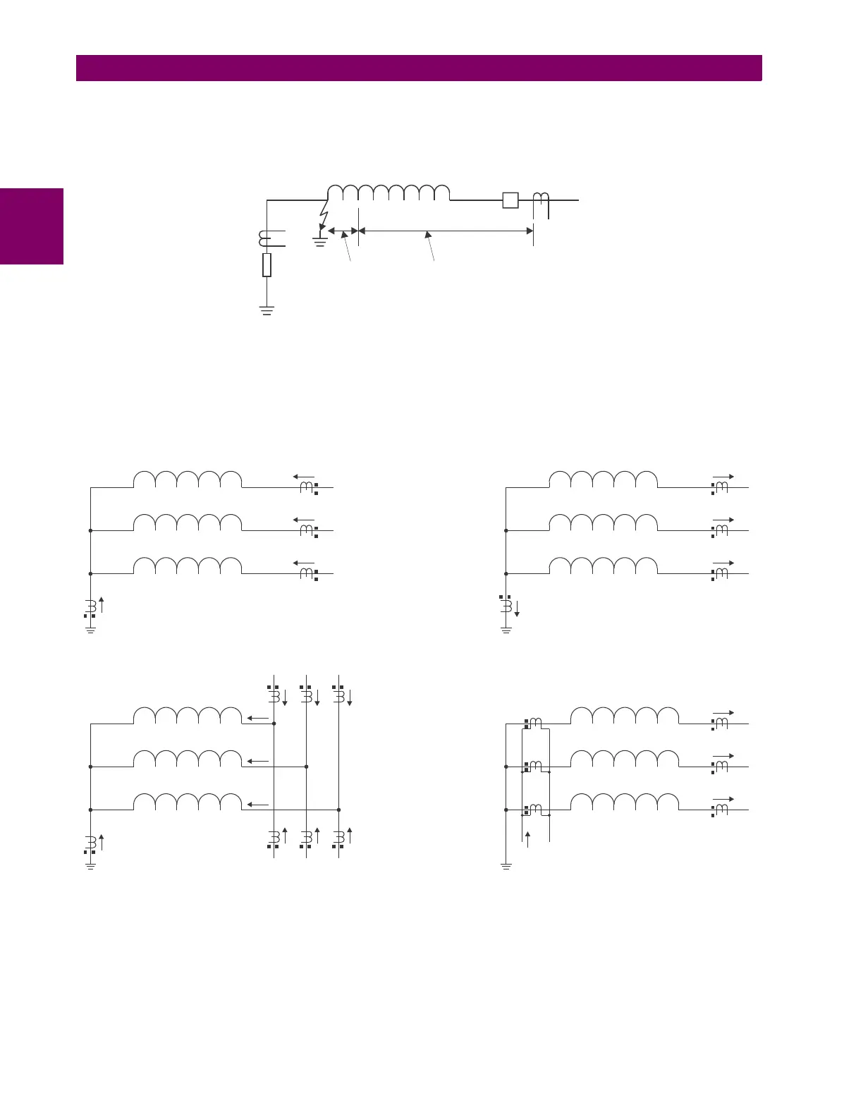
This protection is often applied to transformers having impedance-grounded wye windings. The element may also be
applied to the stator winding of a generator having the neutral point grounded with a CT installed in the grounding path, or
the ground current obtained by external summation of the neutral-side stator CTs. The Typical Applications of RGF Protec-
tion diagram explains the basic application and wiring rules.
Figure 5–118: TYPICAL APPLICATIONS OF RGF PROTECTION
The relay incorporates low-impedance restricted ground fault protection. This low-impedance form of protection faces
potential stability problems. An external phase-to-phase fault is an ultimate case. Ideally, there is neither ground (IG) nor
neutral (IN = IA + IB + IC) current present. If one or more of the phase CTs saturate, a spurious neutral current is seen by
the relay. This is similar to a single infeed situation and may be mistaken for an internal fault. Similar difficulties occur in a
breaker-and-a-half application of the restricted ground fault, where any through fault with a weak infeed from the winding
itself may cause problems.
842731A1.CDR
35%
RGF
ZONE
DIFFERENTIAL ZONE
Rg
WINDING
842732A1.CDR
IG
IG
IA
IA
IB
IB
IC
IC
2
1
2
1
2
1
IG
IG
Transformer Winding
Transformer Winding
(A) Transformer
(B) Transformer in a Breaker-and-a-Half
(C) Stator
(D) Stator without a Ground CT
Stator Winding
Stator Winding
IA
IA
IA
IA
IB
IB
IB
IB
IC
IC
IC
IC

 Loading...


