GE Multilin T60 Transformer Protection System 3-29
3 HARDWARE 3.3 DIRECT INPUT/OUTPUT COMMUNICATIONS
3
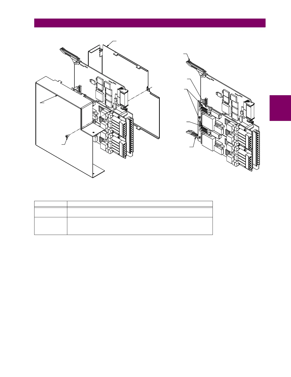
Figure 3–34: G.703 TIMING SELECTION SWITCH SETTING
c) G.703 OCTET TIMING
If octet timing is enabled (ON), this 8 kHz signal is asserted during the violation of bit 8 (LSB) necessary for connecting to
higher order systems. When T60s are connected back-to-back, octet timing is disabled (OFF).
d) G.703 TIMING MODES
There are two timing modes for the G.703 module: internal timing mode and loop timing mode (default).
• Internal Timing Mode: The system clock is generated internally. Therefore, the G.703 timing selection should be in
the internal timing mode for back-to-back (UR-to-UR) connections. For back-to-back connections, set for octet timing
(S1 = OFF) and timing mode to internal timing (S5 = ON and S6 = OFF).
• Loop Timing Mode: The system clock is derived from the received line signal. Therefore, the G.703 timing selection
should be in loop timing mode for connections to higher order systems. For connection to a higher order system (UR-
to-multiplexer, factory defaults), set to octet timing (S1 = ON) and set timing mode to loop timing (S5 = OFF and S6 =
OFF).
Table 3–3: G.703 TIMING SELECTIONS
SWITCHES FUNCTION
S1 OFF octet timing disabled
ON octet timing 8 kHz
S5 and S6 S5 = OFF and S6 = OFF loop timing mode
S5 = ON and S6 = OFF internal timing mode
S5 = OFF and S6 = ON minimum remote loopback mode
S5 = ON and S6 = ON dual loopback mode
Cover screw
Top cover
Bottom cover
Ejector/inserter clip
Ejector/inserter clip
Timing selection
switches
Channel 1
Channel 2
FRONT
REAR
831774A3.CDR