D
IRECTION 5813707-100, REVISION 2 HAWAII™ SERVICE MANUAL
Chapter 5 - Venue Go™Components and Function (Theory) 5-3
PRELIMINARY
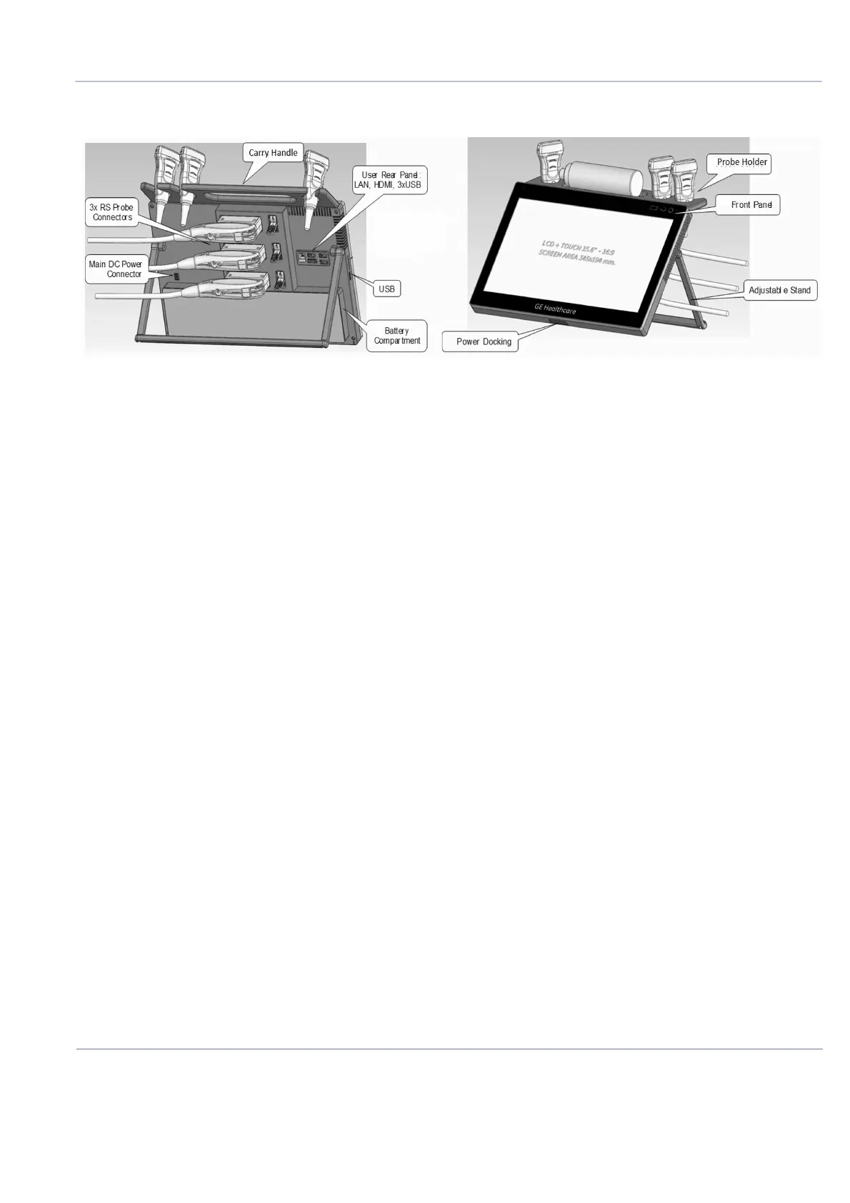
The Venue Go™ system main hardware components are configured as illustrated in Figure 5-1.
The Venue Go™scanner supports the following RS probes:
• Regular RS Probes with up to 128 channels
• Regular RS Probes with Internal Mux
• TEE RS Probes with Temperature sensing (6Tc-RS)
• RS probes with Haystack Needle tracking
• RS probes with control buttons
NOTE: For a detailed description of Venue Go™ system operating modes, refer to the Venue™ User Manual.
The Venue Go™ ultrasound scanner has a software beam-forming system.
Signal flow from the C-PSB to the Front End Board (C-FEB) Electronics, and to the Back End Board
(C-BEB), are finally displayed on the touch display.
5-2-2-1 System Configuration and Software
System configuration is stored on the internal SSD attached to the Back End Unit.
At power up, all necessary software is loaded from the C-BEB SSD.
5-2-2-2 Electronics
The Venue Go™ system internal electronics are divided into three:
• Front End - see page 5 - 11
• Back End - see page 5 - 35
• Venue Go™ Display - see page 5 - 19
The interconnections within the Front End (C-FEB) and the Back End (C-BEB) is via two stacked
connectors (one for power supply and the other one for control and data signals). The display module
is connected via eDP interface to the Back End and additional cable is connected to the Front End
(interface for power management controller - signals for On/Off and indicators).
Figure 5-1 Venue Go™ System - Configuration of Main Hardware Components

 Loading...


