D
IRECTION 5813707-100, REVISION 2 VENUE™ SERVICE MANUAL
8-26 Chapter 8 - Replacement Procedures
PRELIMINARY
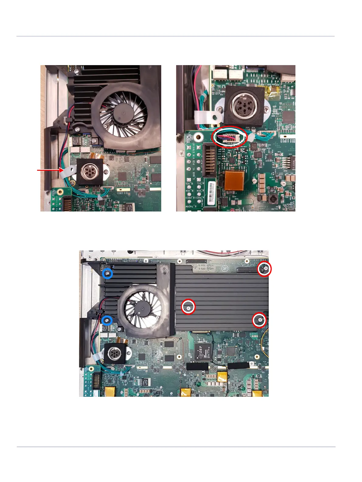
4.) Disconnect the fan cable connector.
5.) Remove the plastic clip holder screw and release the fan cable from the clip.
6.) Release 5 screws connecting the unit (3 flat-head screws, 2 round-head screws marked with blue
circle) and disconnect the Fan.
Figure 8-103 Disconnecting Front Display Indicator Cable
Figure 8-104 Disconnecting C-FEB

 Loading...


