– 26 –
The frequency is monitored by the inverter which
turns off the water valves when the desired water
level is achieved.
Note: The water level will vary depending on the
load size which is measured by the dry load and
wet load sensing cycles. This information is sent
to the inverter, which then determines the
appropriate water level.
Pressure Sensor Test
If the pressure sensor is not operating correctly,
perform the following test:
1. Set the wash cycle to SNEAKERS. This cycle
bypasses the load sensing feature and
defaults to the minimum water level.
2. Measure the water level from the center hub of
the infusor (it should be approximately
2 inches deep in the tub).
3. Set the washer to COMFORTER. This cycle
bypasses the load sensing feature and
defaults to the maximum water level.
4. Measure the water level from the center hub of
the infusor (it should be approximately
11 inches deep in the tub).
Note: Before disconnecting the hose from the
pressure sensor, be sure the water level is below
the bottom of the spin basket.
To remove the pressure sensor:
1. Remove the 2 Phillips head screws that hold
the
Backsplash in place.
2. Place a towel over the lid of the washer to
prevent scratches to the surface. Gently lift
each corner of the backsplash, then roll it
forward so it rests on top of the washer.
3. Remove the 3 Phillips head screws that hold
protective cover in place.
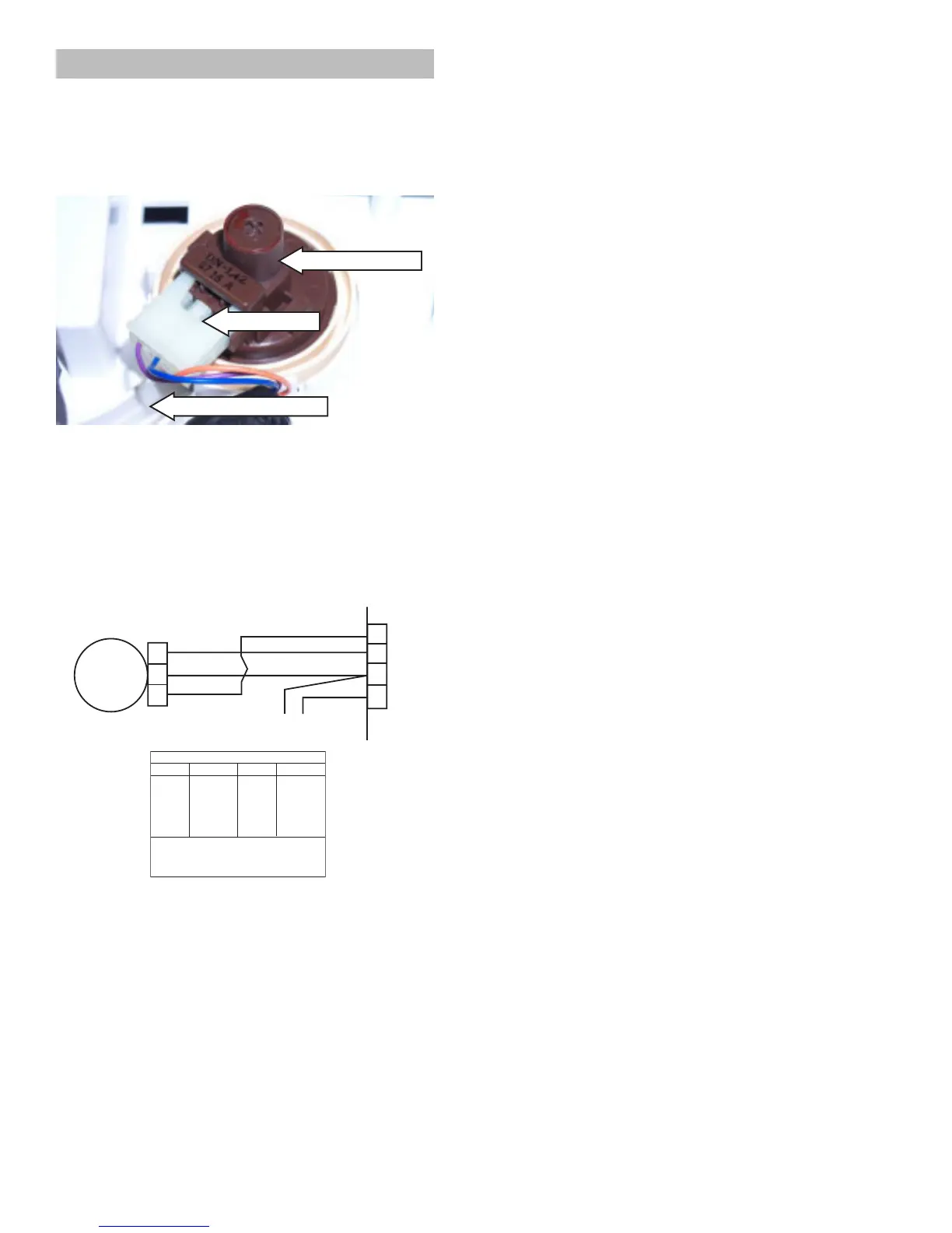
4. Disconnect wiring to the pressure sensor.
5. The pressure sensor is held in place by 3
tabs. With a flat blade screwdriver, press the
tabs back and lift the water level switch up
and out.
6. Disconnect the clear hose from the pressure
sensor.
Pressure Sensor (Water Level Switch)
The pressure sensor is connected by a clear
hose to an air reservoir near the bottom of the
outer tub and operates by a frequency (kHz)
signal to the inverter board.
LID
12
3
4
RX
VX
OX
NX
WX
WX
WX
PRESSURE
S/W
2
1
3
The pressure sensor wires (purple, orange, and
blue) are connected at pins 1, 3, and 4 at the 4-pin
red connector on the inverter board. (See Inverter
and Main Board Pin Connectors).
The approximate resistance value of the
transducer, measured between the purple and
orange wires, is 20 Ω.
• When the water level rises in the washer tub,
air is trapped in the reservoir. As the water
level rises, the air pressure in the reservoir
increases.
• The pressure is translated into an electrical
signal (frequency) by the pressure sensor.
• The frequency will vary from approximately 27
kHz (empty tub) to 22 kHz (full tub).
• This frequency can be measured at the
pressure sensor between the purple and
orange wires.
COLOR CODE
LETTERS COLOR
COLOR
LETTERS
AX
BX
CX
NX
OX
PX
RX
SX
GX
VX
WX
YX
LT. BLUE
BLACK
BROWN
DK.BLUE
ORANGE
PINK
RED
GRAY
GREEN
PURPLE
WHITE
YELLOW
THE "X' INDICATES ONE SOLID COLOR-
NO TRACER. WIRES WITH TRACER SHOW
BOTH COLORS, EXAMPLE - WR IS WHITE
WITH RED TRACER.
Disconnect
Pressure Sensor
Clear Pressure Hose