– 34 –
To remove the rotor and stator:
WARNING: The rotor is not grounded. Unplug the
washer before servicing to avoid electrical shock
1. To access the motor, the washer must be
placed on its side. Place a towel or blanket on
the floor to prevent scratches to the surface
of the washer.
2. Remove the 24-mm (
15
/16 in. SAE equivalent)
rotor nut with a socket or open end Crescent
wrench (rotate rotor nut counterclockwise to
remove).
Note: Use a rubber mallet if needed to tap the
wrench to break the nut free.
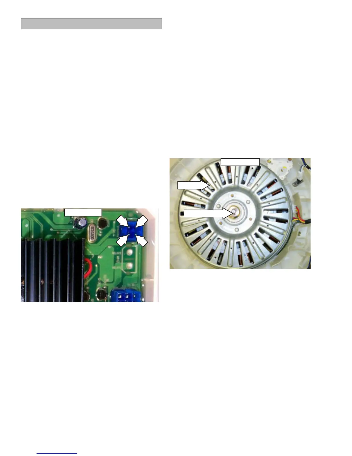
Rotor Nut
Bottom view
Rotor
Hall Sensor
• The Hall effect sensor measures the motor
rpm.
• Four wires connect the Hall sensor to the
inverter board at the 4-pin dark blue
connector. (See
Inverter and Main Board Pin
Connectors.)
• The Hall sensor measures approximately
9K Ω between the brown and blue wires and
the brown and red wires.
• If the sensor has failed, the motor will not
operate.
• The Hall sensor is part of the stator assembly.
It is not available as a separate part.
To check the Hall sensor voltage at the inverter:
• Disconnect the Hall sensor plug from the
inverter board. Check voltage on pins
3 (brown) and 4 (yellow) on the inverter board.
There should be approximately 12 VDC. If not,
the inverter board is bad.
To check voltage at the Hall sensor:
• Measure between pins 1 (blue) and 4 (yellow)
and pins 2 (red) and 4 (yellow) with the Hall
sensor plugged into the inverter board. Rotate
the spin basket by hand. There should be
12-VDC pulses as the basket is rotated. If
pulses are present, the Hall sensor is good.
3
1
4
2
Inverter Board