226
II. Inspection
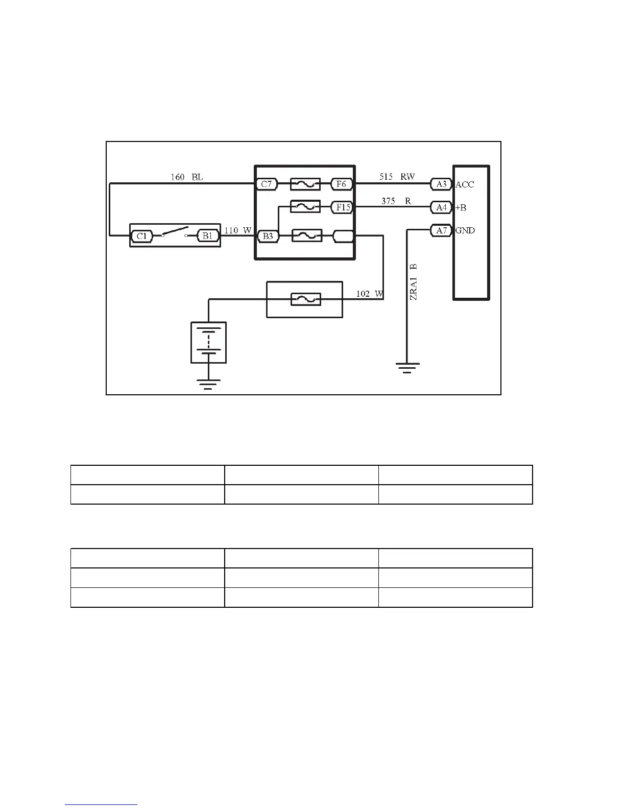
1. Power switch system doesn't work
Wiring Diagram
(1) Check radio assembly (+B, ¬ACC, ¬GND)
1 Check the continuity between terminals under each operating condition as shown in the table below
Standard:
2 Check the voltage between terminals under each operating condition as shown in the table
Standard:
Normal: Repair or replace wire harness, connector
Abnormal: Check or replace radio assembly
Main Fuse Box
Radio and CD
Battery
Fusible Link Box
Ignition Switch
Tester connection Condition Standard Status
GND Constant Status Continuity
Tester Connection Condition Standard Status
+B - GND Constant Status 10
~
14V
ACC - GND Ignition switch ACC or ON 10
~
14V