ADV200 • Functions description and parameters list 65
Menu PAR Description UM Type FB BIT Def Min Max Acc Mod
14.11 1520Analoginp1thr INT16 0 -16384 + 16383 ERW FVS
14.27 1570Analoginp2thr INT16 0 -16384 + 16383 ERW FVS
Setting of the analog input threshold for the speednotexceeded signal, which allows enabling of the digital
outputs Analoginp1(par. 1530) and Analoginp2(par.1580).
Analog inp x thr
x = 1, 2
Analog inp x <thr
Analog inp x thr
Analog inp x <thr
Menu PAR Description UM Type FB BIT Def Min Max Acc Mod
14.12 1522Aninp1deadband perc FLOAT 0 0 100.0 ERW FVS
14.28 1572Aninp2deadband perc FLOAT 0 0 100.0 ERW FVS
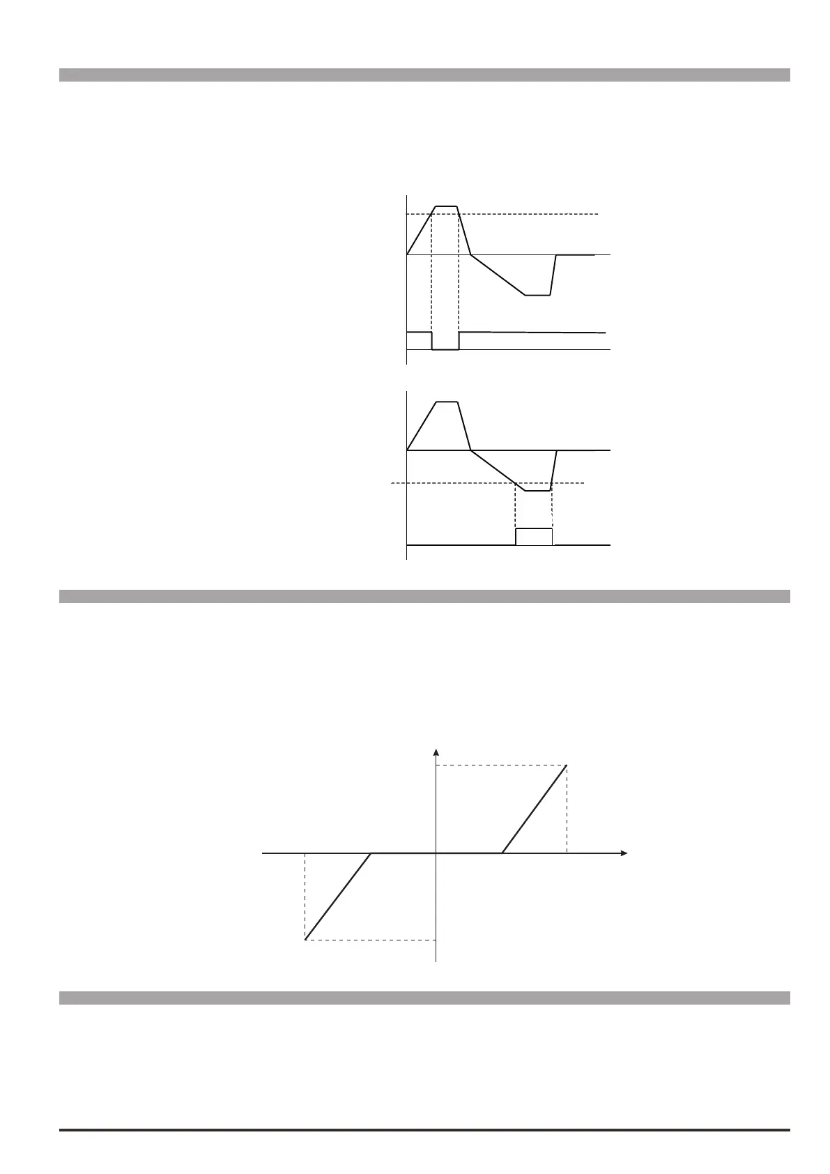
Deadband referring to the analog input signal. When the value on the input terminal is below the threshold de-
ned by the parameter, the output signal of the analog input block is forced to zero. Outside the deadband, the
block output varies linearly from zero to 100%.
AnInp Drive
AnInp Terminal
100%
-100%
10V
-10V
100%
-100%
Par.1522=50%
Par.1522=50%
Menu PAR Description UM Type FB BIT Def Min Max Acc Mod
14.13 1524Aninp1altvalue cnt INT16 16/32 0 -16384 16384 ERW FVS
14.29 1574Aninp2altvalue cnt INT16 16/32 0 -16384 16384 ERW FVS
Setting of a xed alternative value for the relative analog input, which can be selected via a command enabled
by a digital input programmed with the Aninpaltselsrc parameter.

 Loading...


