70 ADV200 • Functions description and parameters list
There is no single Unit suitable for all models of analog input module. Check the scaling provided by the model
being used and use the system variables accordingly.
Analog input 0 and analog input 1 can also be managed by the drive parameters. To ensure correction opera-
tion, the scaling provided by the external module must be compatible with the scaling requested by the drive.
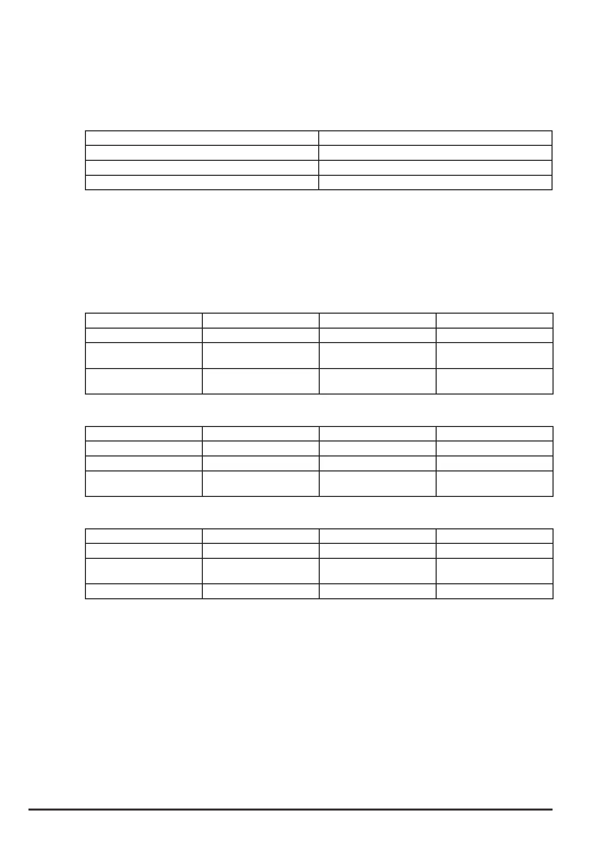
The drive needs I/O modules that supply datum scaled as follows
AnaloginpXtype Range
-10V..+10V -32768..+32767
0V..+10V 0..+65535
4..20mA +13107..+65535
When the AninpXgaintune (PAR 1508, PAR1558) command is sent with analog input set to the maximum
value, the gain needed to adjust the full scale value is calculated.
For modules with scaling other than that requested by the drive, the AninpXgaintune command attempts to
adjust the scaling. For that reason the maximum value is increased for AninpXgaintune parameters.
The tables below show the output of the analog input block according to the signal connected and the congu-
ration of the AnaloginpXtypeparameter (PAR 1502, PAR1552).
Signalconnected:-10V..+10V
Aninputtype -10V 0V +10V
-10V..+10V Bottom Obtained from straight line Top
0V..+10V Less than 0V saturation at
Bottom
Bottom Top
4.0.20mA Less than 2V saturation at
Bottom
Bottom Top
Signalconnected:0V..+10V
Aninputtype 0V +10V
-10V..+10V Obtained from straight line Top
0V..+10V Bottom Top
4..20mA Less than 2V saturation at
Bottom
Top
Signalconnected:4..20mA
Aninputtype 4mA 20mA
-10V..+10V Top
0V..+10V Less than 4 mA saturation at
Bottom
Top
4..20mA Bottom Top
The Analog inputs voltage or current inputs must be congured on the external module using a dedicated
switch or tool. For analog input 0 and analog input 1 the An input type parameter must be set according to the
type of external device.

 Loading...


