• Do NOT perform a dielectric voltage withstand test (Megger) on the inverter this will result in inverter dam-
age to the semiconductor components.
• Do NOT touch any of the components on the inverter control board to prevent damage to the inverter by
static electricity.
• Refer to the recommended wire size table for the appropriate wire to use. The voltage between the power
supply and the input terminals of the inverter may not exceed 2%.
Phase-to-phase voltage drop (V) = √3 ×resistance of wire (Ω/km) × length of line m) × current×10
-3
.
(km=3280 x feet) / (m=3.28 x feet )
• Reduce the carrier frequency (parameter 11-01) If the cable from the inverter to the motor is over 25m
(82ft). A high-frequency current can be generated by stray capacitance between the cables and result in an
overcurrent trip of the inverter, an increase in leakage current, or an inaccurate current readout.
• To protect peripheral equipment, install fast acting fuses on the input side of the inverter. Refer to section
11.4 for additional information (on VDI100 Instruction Manual).
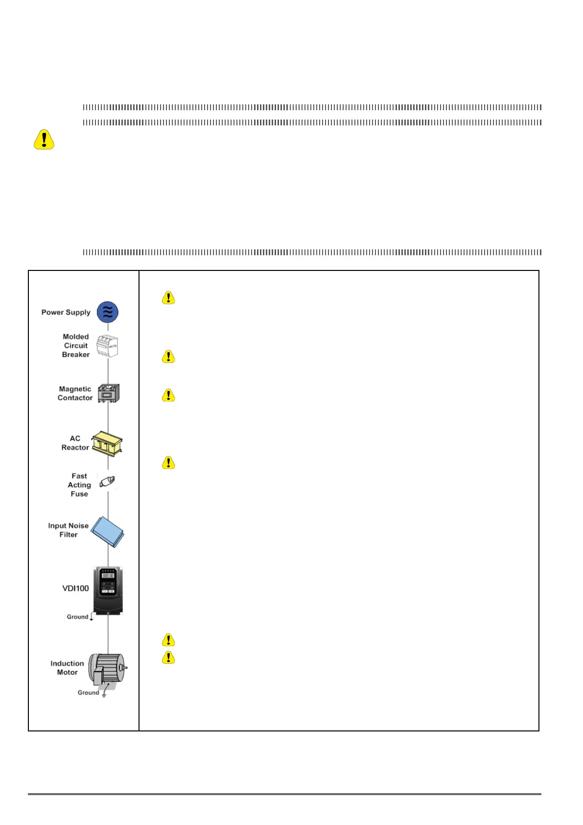
Power supply:
•
Make sure the correct voltage is applied to avoid damaging the inverter.
Molded-case circuit breaker (MCCB) or fused disconnect:
• A molded-case circuit breaker or fused disconnect must be installed between the AC source and the inverter that
conforms to the rated voltage and current of the inverter to control the power and protect the inverter.
•
Do not use the circuit breaker as the run/stop switch for the inverter.
Ground fault detector / breaker:
•
Install a ground fault breaker to prevent problems caused by current leakage and to protect personnel. Select
current range up to 200mA, and action time up to 0.1 second to prevent high frequency failure.
Magnetic contactor:
• Normal operations do not need a magnetic contactor. When performing functions such as external control and auto
restart after power failure, or when using a brake controller, install a magnetic contactor.
•
Do not use the magnetic contactor as the run/stop switch for the inverter.
AC line reactor for power quality:
• When inverters are supplied by a high capacity power source (> 600kVA), an AC reactor can be connected to improve
the power factor.
Install Fast Acting Fuse:
• To protect peripheral equipment, install fast acting fuses in accordance with the specifications in section 11.4 (on
VDI100 Instruction Manual).
Input Noise filter:
• A filter must be installed when there are inductive loads affecting the inverter. The inverter meets EN 61800-3:2012,
category C3 or C2 when the Gefran special filter is used. See section 11.3 on VDI100 Instruction Manual.
Inverter:
• Output terminals T1, T2, and T3 are connected to U, V, and W terminals of the motor. If the motor runs in reverse while
the inverter is set to run forward, swap any two terminals connections for T1, T2, and T3.
•
To avoid damaging the inverter, do not connect the output terminals T1, T2, and T3 to AC input power.
•
Connect the ground terminal properly. (Rg <10Ω.)
Motor:
• If the inverter drives multiple motors the output rated current of the inverter must be greater than the total current of all
the motors.
Caution
12 VDI100 • Start-up and Installation Manual

 Loading...
