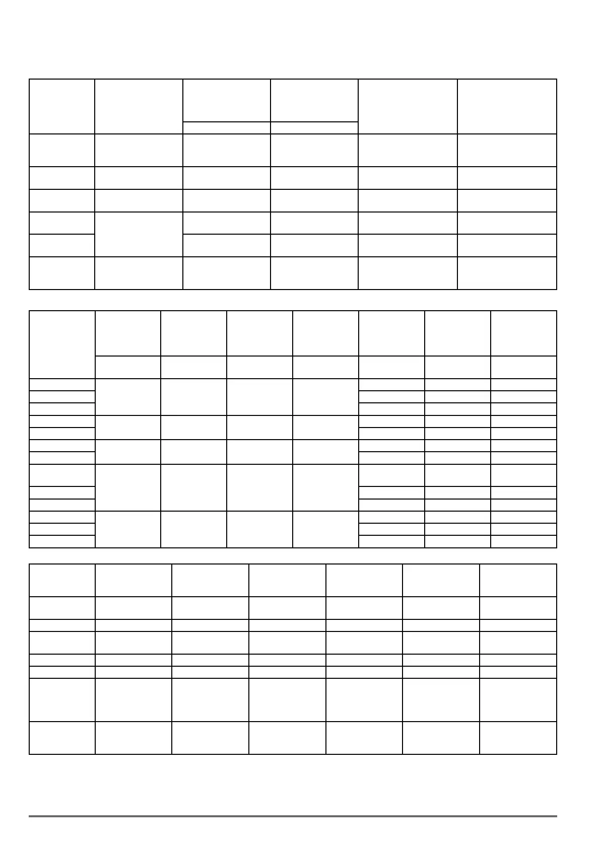
4.2.1. Attachment 1: Parameters’ default value and upper limit value are adjusted by different capaci-
ties of inverter
Models Size
Max. frequency in SLV
when carrier frequency
≤ 8 kHz
11-01
Max. frequency (Hz)
in SLV when carrier
frequency > 8 kHz
11-01
Display parameter 12-41
(Inverter temperature)
The initial value of pa-
rameter 18-00 in SLV/ SV
(Slip compensation at low
speed)
(Hz) (Hz)
1007
1015
1022
1 150 150 Yes 1.00
2037
2055
2 150 150 Yes 1.00
3075
3110
3 150 150 Yes 1.00
3150
4150
4
110 110 Yes 1.00
4185
4220
100 100 Yes 1.00
5300
5370
5450
5 100 80 Yes 0.70
Models
The initial value
of parameters
21-05 ~21-08
The initial value
(s) of parameter
20-08
The initial value
(V) of parameter
08-02
The initial value
of Accel. & Decel
00-14~00-17 &
00-23~00-27
Default carrier
in HD
11-01
Max. carrier
in HD
11-01
Max. carrier
in HD
11-01
(Torque Limit) (ASR Filter Time)
(Stall Level in
Deceleration)
(s) kHz
kHz (SLV, Max. >
80Hz)
kHz
(others)
1007
200% 0.001 770 10.0
8 8 16
1015 8 8 16
1022 8 8 16
2037
200% 0.001 770 10.0
8 8 16
2055 8 8 16
3075
200% 0.001 770 10.0
8 8 16
3110 8 8 16
3150
4150
200% 0.002 770 15.0
8 8 16
4185 8 8 16
4220 8 8 16
5300
160% 0.002 770 20.0
5 8 12
5370 5 8 12
5450 5 8 10
Model
01-09
Minimum Output Volt-
age 1 of Motor 1
01-07
Middle Output
Voltage 1 of Motor 1
01-23
Minimum Output Volt-
age 1 of Motor 2
01-21
Middle Output
Voltage 1 of Motor 2
11-59
Gain of Preventing
Oscillation
11-60
Upper Limit of
Preventing Oscillation
1007
1015
15.8V 25.6V 15.8V 25.6V 0.05 100
1022 15.0V 28.0V 15.0V 28.0V 0.05 100
2037
2055
15.0V 28.0V 15.0V 28.0V 0.05 100
3075 15.0V 28.0V 15.0V 28.0V 0.05 100
3110 15.0V 28.0V 15.0V 28.0V 0.05 10
3150
4150
4185
4220
15.0V 28.0V 15.0V 28.0V 0.01 10
5300
5370
5450
17.0V 30.0V 17.0V 30.0V 0.01 10
64 VDI100 • Start-up and Installation Manual

 Loading...
