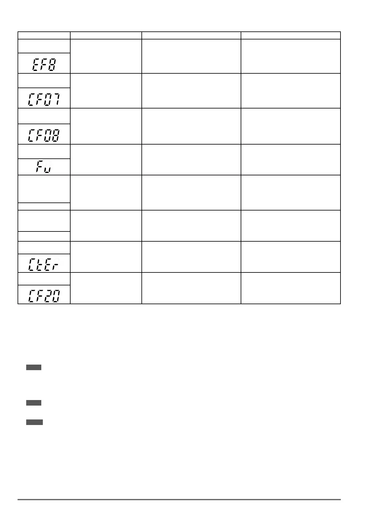
LED display Description Cause Possible solutions
EF8
External fault (S8)
External fault (Terminal S8) Active
when 03-07= 25, and Inverter
external fault selection 08-24=0
or 1.
• Multifunction digital input external fault
active.
• Multi-function input function set incorrectly.
• Check wiring
CF07
Motor control fault
Motor control fault • SLV mode is unable to run motor
•Perform rotational or stationary auto-tune
•Increase minimum output frequency (01-08
CF08
Motor control fault
Motor control fault •Start or Run fault in PMSLV mode
•Increase the value of 22-10 properly.
•Re auto-tune (22-21).
•Check if the load is too heavy to raise torque
output limit.
FU
fuse open
DC bus fuse blown
• IGBT damaged.
• Short circuit output terminals.
•Check IGBTs
•Check for short circuit at inverter output.
•Replace inverter.
CF00
Operator
Communication Error
Errors of data transmission occur
in LCD keypad
• LCD keypad and inverter cannot transmit data
after power on 5 seconds
•Disconnect the operator and then reconnect.
•Replace the control board
LCD display only *
CF01
Operator Communica-
tion Error 2
Errors of data transmission occur
in LCD keypad
• LCD keypad and inverter can transmit data
but transmission error occurs for more than 2
seconds
•Disconnect the operator and then reconnect.
•Replace the control board
LCD display only *
CTER
CT Failure
Errors of detecting voltages
from three phase’s current
transformer to detect output
current.
• Errors of detecting voltages
• Noises too much
• Control board failure
• Check current transformer signal and the
voltage on the control board.
CF20
Communication Failure
Use Profibus & Modbus
Communication at the same time.
• Maybe use two kind of communication type
at the same time.
• Check only use one kind of communication
type.
* When the communication errors occur in LED keypad (KB-LED-VDI100), the LED will stay the screen and stop action.
5.3. Warning / Self-diagnosis Detection Function
When the inverter detects a warning, the keypad displays a warning code (ash).
Note: The fault contact output does not energize on a warning and the inverter continues operation. When the warning is no longer
active the keypad will return to its original state.
When the inverter detected a programming error (for example two parameters contradict each other of are set
to an invalid setting), the keypad displays a self-diagnostics code.
Note: The fault contact output does not energize on a self-diagnostics error. While a self-diagnostics code is active the inverter does not
accept a run command until the programming error is corrected.
Note: When a warning or self- diagnostic error is active the warning or error code will flash on the keypad.
When the RESET key is pressed, the warning message (ash) disappears and returns after 5 sec. If the warn-
ing or self-diagnostic error still exists.
Refer to Table 10.3.1 for and overview, cause and corrective action for inverter warnings and self-diagnostic
errors.
68 VDI100 • Start-up and Installation Manual

 Loading...
