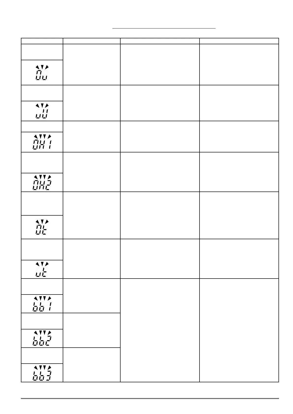
Table 10.3.1 warning / self-diagnosis and corrective actions
LED display Description Possible causes Corrective action
OV
(flash)
Over voltage
DC bus voltage exceeds the OV
detection level (820Vdc).
(If input voltage 01-14 is set lower
than 400V, the OV detection value
will is decreased to 700Vdc)
•Deceleration time set too short, resulting in
regenerative energy flowing back from motor to
the inverter.
•The inverter input voltage is too high.
•Use of power factor correction capacitors.
•Excessive braking load.
•Braking transistor or resistor defective.
•Speed search parameters set incorrectly.
•Increase deceleration time
•Reduce input voltage to comply with the
input voltage requirements or install an AC line
reactor to lower the input voltage.
•Remove the power factor correction capacitor.
•Use dynamic braking unit.
•Replace braking transistor or resistor.
•Adjust speed search parameters.
UV
(flash)
under voltage
DC bus voltage is lower than the
UV detection level (380Vdc) or the
pre-charge contactor is not active
while the inverter is running.
(the detection value can be
adjusted by 07-13)
•The input voltage is too low.
•Input phase loss.
•Acceleration time set too short.
•Input voltage fluctuation.
•Pre-charge contactor damaged.
•DC bus voltage feedback signal value not
incorrect.
•Check the input voltage.
•Check input wiring.
•Increase acceleration time.
•Check power source
•Replace pre-charge contactor
•Replace control board or complete inverter
OH1
Heatsink overheat
The temperature of the heat sink
is too high.
Note: when OH1 fault occurs
three times within five minutes,
it is required to wait 10 minutes
before resetting the fault.
•Ambient temperature too high.
• cooling fan failed
• Carrier frequency set too high.
• Load too heavy.
•Install fan or AC to cool surroundings.
•Replace cooling fan.
•Reduce carrier frequency.
•Reduce load / Measure output current
OH2
(flash)
Inverter over heating
warning
Inverter overheat warning Mul-
ti-function digital input set to 31.
(Terminal S1 ~ S8) Active when
03-00 ~ 03-07 = 31).
• Multifunction digital input overheat warning
active.
•Multi-function input function set incorrectly.
•Check wiring
OT
(flash)
over torque detection
Inverter output torque is higher
than 08-15 (over torque detection
level) for the time specified in
08-16. Parameter 08-14 = 0 to
activate.
•Load too heavy.
•Check over torque detection parameters (08-
15 / 08-16).
•Check and reduce motor load, check and
operation duty cycle.
UT
(flash)
under torque
detection
Inverter output torque is lower
than 08-19 (under torque detec-
tion level) for the time specified
in 08-20. Parameter 08-18 = 0 to
activate.
•Sudden drop in load.
•Belt break.
•Check under torque detection parameters
(08-19 / 08-20).
•Check load / application.
bb1
(flash)
External baseblock
External base block
(Terminal S1)
•Multifunction digital input external baseblock
active
•Multi-function input function set incorrectly.
•Check wiring
bb2
(flash)
External baseblock
External base block
(Terminal S2)
bb3
(flash)
External baseblock
External base block
(Terminal S3)
VDI100 • Start-up and Installation Manual 69

 Loading...
