3. Environment and Installation
3.1. Wire Gauges and Tightening Torque
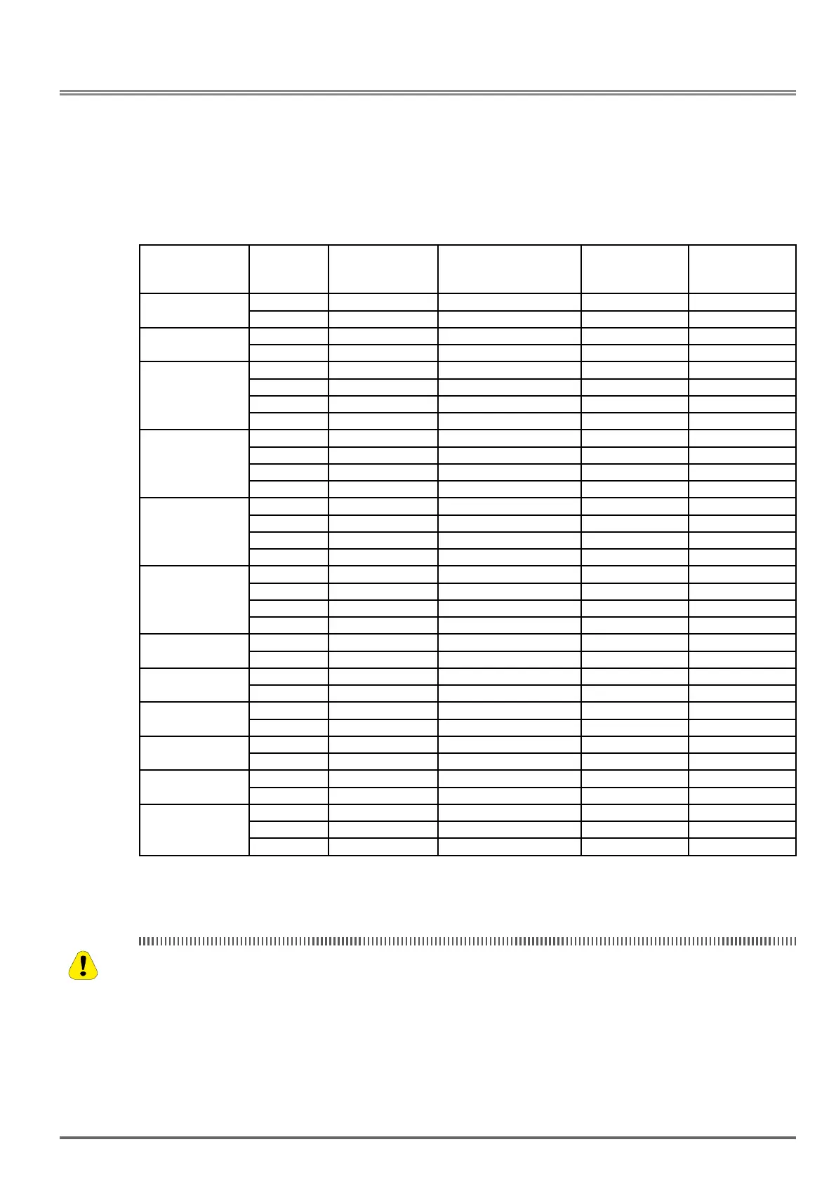
To comply with UL standards, use UL approved copper wires (rated 75° C) and round crimp terminals (UL List-
ed products) as shown in table below when connecting to the main circuit terminals. Gefran recommends using
crimp terminals manufactured by NICHIFU Terminal Industry Co., Ltd and the terminal crimping tool recom-
mended by the manufacturer for crimping terminals and the insulating sleeve.
Wire size
Terminal
screw size
Model of the round
crimp terminal
Fastening torque
Model of insulating
sleeve
Model of
crimp tool
mm
2
(AWG) kgf.cm (in.lbs)
0.75 (18)
M3.5 R1.25-3.5 8.2 to 10 (7.1 to 8.7) TIC 1.25 NH 1
M4 R1.25-4 12.2 to 14 (10.4 to 12.1) TIC 1.25 NH 1
1.5 (16)
M3.5 R1.25-3.5 8.2 to 10 (7.1 to 8.7) TIC 1.25 NH 1
M4 R1.25-4 12.2 to 14 (10.4 to 12.1) TIC 1.25 NH 1
2.5 (14)
M3.5 R2-3.5 8.2 to 10 (7.1 to 8.7) TIC 2 NH 1 / 9
M4 R2-4 12.2 to 14 (10.4 to 12.1) TIC 2 NH 1 / 9
M5 R2-5 22.1 to 24 (17.7 to 20.8) TIC 2 NH 1 / 9
M6 R2-6 25.5 to 30.0 (22.1 to 26.0) TIC 2 NH 1 / 9
4.0 / 6.0 (12/10)
M4 R5.5-4 12.2 to 14 (10.4 to 12.1) TIC 5.5 NH 1 / 9
M5 R5.5-5 20.4 to 24 (17.7 to 20.8) TIC 5.5 NH 1 / 9
M6 R5.5-6 25.5 to 30.0 (22.1 to 26.0) TIC 5.5 NH 1 / 9
M8 R5.5-8 61.2 to 66.0 (53.0 to 57.2) TIC 5.5 NH 1 / 9
10.0 (8)
M4 R8-4 12.2 to 14 (10.4 to 12.1) TIC 8 NOP 60
M5 R8-5 20.4 to 24 (17.7 to 20.8) TIC 8 NOP 60
M6 R8-6 25.5 to 30.0 (22.1 to 26.0) TIC 8 NOP 60
M8 R8-8 61.2 to 66.0 (53.0 to 57.2) TIC 8 NOP 60
16 (6)
M4 R14-4 12.2 to 14 (10.4 to 12.1) TIC 14 NH 1 / 9
M5 R14-5 20.4 to 24 (17.7 to 20.8) TIC 14 NH 1 / 9
M6 R14-6 25.5 to 30.0 (22.1 to 26.0) TIC 14 NH 1 / 9
M8 R14-8 61.2 to 66.0 (53.0 to 57.2) TIC 14 NH 1 / 9
25 (4)
M6 R22-6 25.5 to 30.0 (22.1 to 26.0) TIC 22 NOP 60/ 150H
M8 R22-8 61.2 to 66.0 (53.0 to 57.2) TIC 22 NOP 60/ 150H
35 (2)
M6 R38-6 25.5 to 30.0 (22.1 to 26.0) TIC 38 NOP 60/ 150H
M8 R38-8 61.2 to 66.0 (53.0 to 57.2) TIC 38 NOP 60/ 150H
55 (1/0)
M8 R60-8 61.2 to 66.0 (53.0 to 57.2) TIC 60 NOP 60/ 150H
M10 R60-10 102 to 120 (88.5 to 104) TIC 60 NOP 150H
70 (2/0)
M8 R70-8 61.2 to 66.0 (53.0 to 57.2) TIC 60 NOP 150H
M10 R70-10 102 to 120 (88.5 to 104) TIC 60 NOP 150H
95 (3/0)
M10 R80-10 102 to 120 (88.5 to 104) TIC 80 NOP 150H
M16 R80-16 255 to 280 (221 to 243) TIC 80 NOP 150H
120 (4/0)
M10 R100-10 102 to 120 (88.5 to 104) TIC 100 NOP 150H
M12 R100-12 143 to 157 (124 to 136) TIC 100 NOP 150H
M16 R80-16 255 to 280 (221 to 243) TIC 80 NOP 150H
3.2. Wiring Peripheral Power Devices
• After power is shut off to the inverter the capacitors will slowly discharge. Do NOT touch the inverter circuit
or replace any components until the “CHARGE” indicator is off.
• Do NOT wire or connect/disconnect internal connectors of the inverter when the inverter is powered up or
after power off but the “CHARGE”” indicator is on.
• Do NOT connect inverter output U, V and W to the AC power source. This will result in damage to the
inverter.
• The inverter must be properly grounded. Use terminal E to connect earth ground and comply with local
standards.
• It is required to disconnect the ground wire in the control board if the inverter is not grounded.
Caution
VDI100 • Start-up and Installation Manual 11

 Loading...
