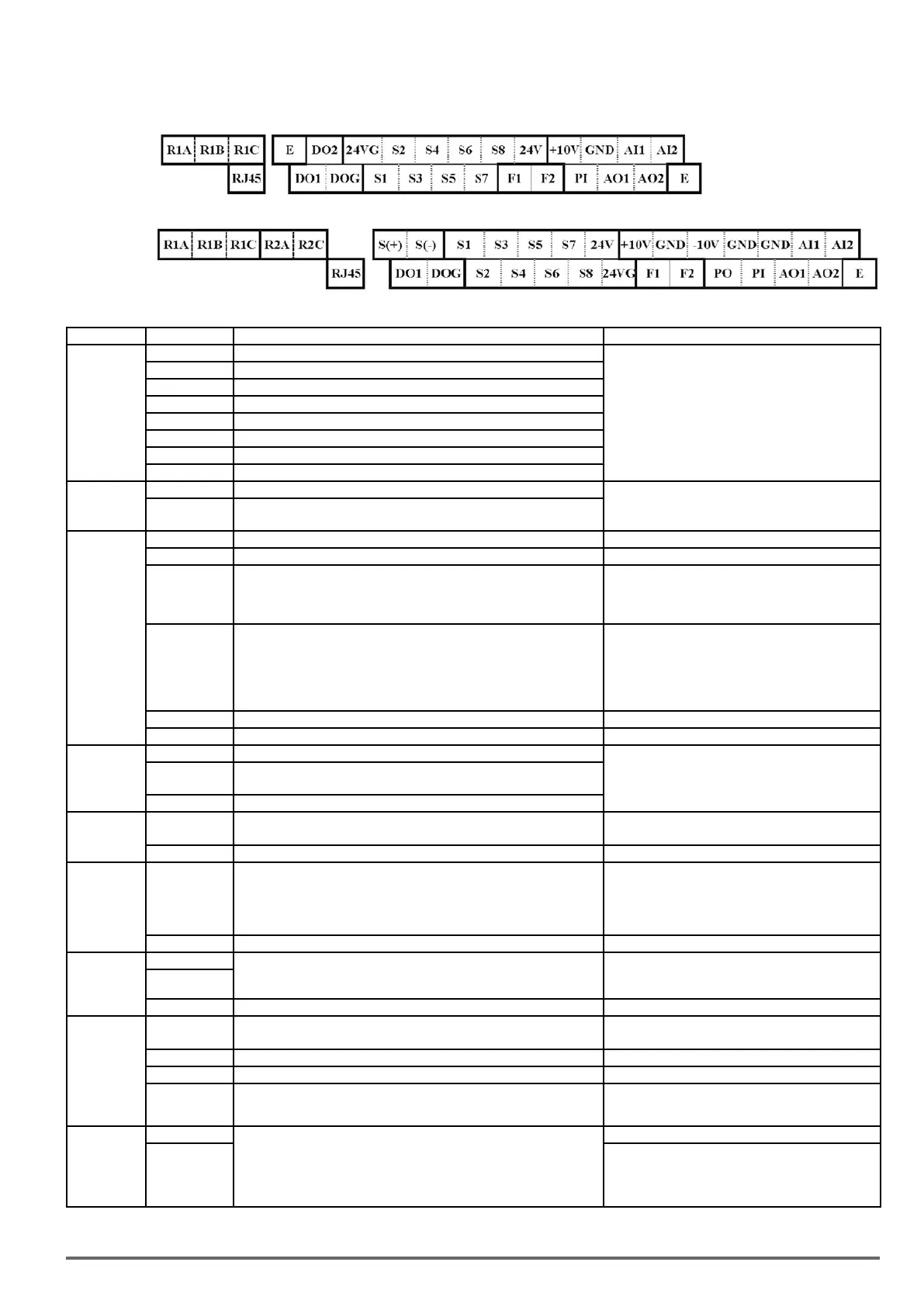
3.5. User Terminals (Control Circuit Terminals)
0.75 ~ 2.2kW
3.7~45kW
Description of User Terminals
Type Terminal Terminal Function Signal Level / Information
Digital input
signal
S1 2-wire forward/ stop (default) * 1
Signal Level 24 VDC
(photo isolated)
Maximum current: 8mA
Maximum voltage: 30 Vdc
Input impedance: 4.22kΩ
S2 2-wire reversal/ stop (default) * 1
S3 Multi-speed/ position setting command 1 (default) * 1
S4 Multi-speed/ position setting command 2 (default) * 1
S5 Multi-speed/ position setting command 3 (default) * 1
S6 Fault reset (default) * 1
S7 JOG frequency command (default) * 1
S8 External B.B.(Base Block) stop (coast to stop) (default) * 1
24V Power
supply
24V Digital signal SOURCE point (SW3 switched to SOURCE )
±15%,
Max. output current: 250mA
(The sum of all loads connected )
24VG
Common terminal of Digital signals
Common point of digital signal SINK ( SW3 switched to SINK )
Analog input
signal
+10V Power for external speed potentiometer +10V (Max. current , 20mA)
-10V Only above 3.7kW (include) support this terminal function -10V (Max. current , 20mA)
AI1
Multi-function analog input for speed reference (0-10V input)/
(-10V~10V input)
From 0 to +10V,
From -10V to +10V
Input impedance : 20KΩ
Resolution: 11bit + 1
AI2
Multi-function analog input terminals *2, can use SW2 to switch voltage
or current input (0~10V)/(4-20mA)
From 0 to +10V,
From -10V to +10V
Input impedance: 200KΩ
From 4 to 20 mA
Input impedance: 250KΩ
Resolution: 11bit + 1
GND Analog signal ground terminal ----
E Shielding wire’s connecting terminal (Ground) ----
Analog output
signal
AO1 Multi-function analog output terminals *2 (0~10V output)
From 0 to 10V, From 4 to 20mA
(Load < 500Ω)
PWM Frequency: 10KHz
AO2
Multi-function analog output terminals *2. can use SW6 to switch
voltage or current input (0~10V / 4-20mA output)
GND Analog signals ground terminal
Pulse output
signal
PO
Pulse output, Band width 32KHz, only above 3.7kW (include) support
this terminal function.
Max. Frequency: 32KHz
Open Collector output
GND Analog signals ground terminal ----
Pulse input
signal
PI
Pulse command input,
Bandwidth: 32KHz
L: from 0.0 to 0.5V
H: from 4.0 to 13.2V
Max. Frequency: 0 - 32KHz
Built-in pull-up resistance. When open collector input
is used, it is not required to connect resistance.
GND Analog signals ground terminal ----
Digital output
DO1
Multi-function(open collector transistor) output *1
48Vdc, 2~50mA
Open-collector output
DO2
(Frame one only)
DOG Open collector transistor digital ground
Relay output
R1A
Relay A contact (multi-function output terminal)
Relay B contact (multi-function output terminal)
Rating: 250Vac, 10 mA ~ 1A
30Vdc, 10 mA ~ 1A
R1B Relay contact common terminal,
R1C With the same functions as DO1/DO2
R2A-R2C
(Frame 2 and
above)
With the same functions as DO1/DO2
Rating: 250Vac, 10 mA ~ 1A
30Vdc, 10 mA ~ 1A
Run Permis-
sive Input
F1 On: normal operation.
Off: stop. (Jumper wired between F1 and F2 has to be removed by using
external contact to stop.)
Activation of this input will switch off the inverter output causing the
motor to coast to stop.
24Vdc, 8mA, pull-up
F2 24V Ground
VDI100 • Start-up and Installation Manual 15

 Loading...
