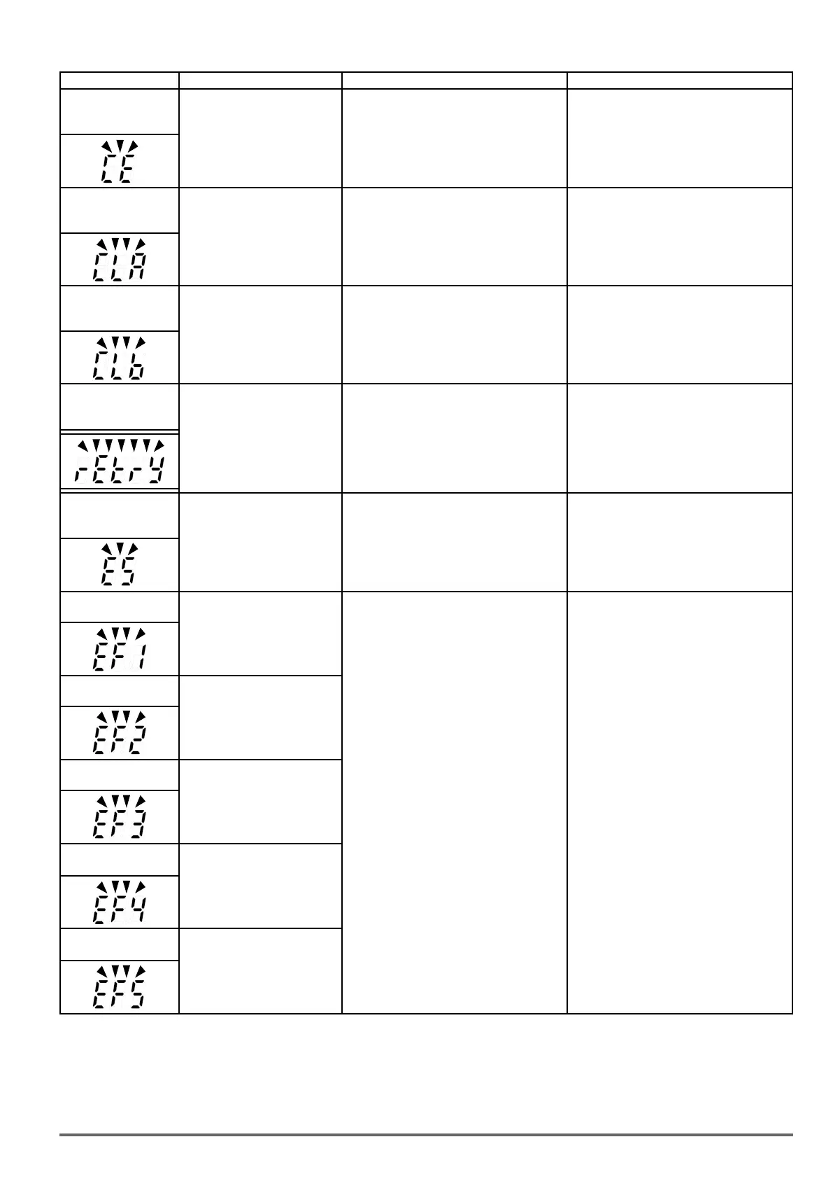
LED display Description Possible causes Corrective action
CE
(flash) communication
error
No Modbus communication
received for 2 sec.
Active when 09-07=3.
• Connection lost or wire broken.
• Host stopped communicating.
• Check connection
• Check host computer / software
CLA
over current protection
level A
Inverter current reaches the
current protection level A.
• Inverter current too high.
• Load too heavy. • Check load and duty cycle operation.
CLB
over current protection
level B
Inverter current reaches the
current protection level B.
• Inverter current too high.
• Load too heavy. • Check load and duty cycle operation.
Retry
(flash)
retry
Automatic reset activated, warn-
ing is displayed until restart delay
time set (07-01) expires.
• Parameter 07-01 set to a value greater than 0.
• Parameter 07-02 set to a value greater than 0.
•Warning disappears after automatic reset.
ES (flash)
External emergency
stop
External emergency stop Enabled.
• 03-00~03-08 set to 14, and the digital input
enabled.
• Turn off run command, and remove external
emergency stop command.
EF1 ( flash )
External fault (S1)
External fault (Terminal S1) Active
when 03-00= 25, and Inverter
external fault selection 08-24=2.
• Multifunction digital input external fault active
and parameter 08-24 = 2 for operation to
continue.
• Multi-function input function set incorrectly.
• Check wiring
• Multi-function input function set incorrectly.
• Check wiring
EF2 ( flash )
External fault (S2)
External fault (Terminal S2) Active
when 03-01= 25, and Inverter
external fault selection 08-24=2.
EF3 ( flash )
External fault (S3)
External fault (Terminal S3) Active
when 03-02= 25, and Inverter
external fault selection 08-24=2.
EF4 ( flash )
External fault (S4)
External fault (Terminal S4) Active
when 03-03= 25, and Inverter
external fault selection 08-24=2.
EF5 ( flash )
External fault (S5)
External fault (Terminal S5) Active
when 03-04= 25, and Inverter
external fault selection 08-24=2.
VDI100 • Start-up and Installation Manual 71

 Loading...
