Chap. 4 — page 15
L.GEISMAR Company – Prohibited Reproduction©
HYDRAULIC RAIL THREADER H90461 / NO 10055
TYPE MPR – M
4 – 4 Hydraulic controls
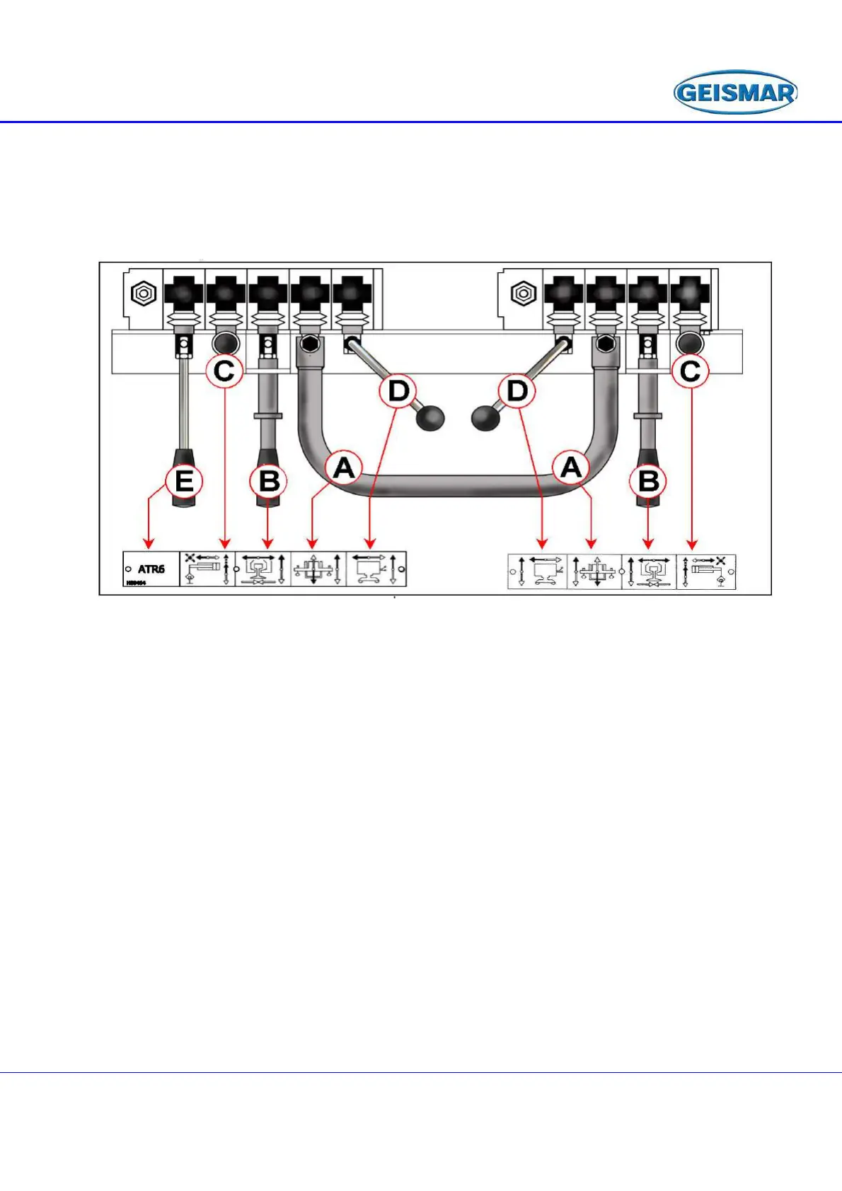
The hydraulic controls (fig. 3) consist of three manually-controlled hydraulic
distributor blocks with built-in pressure limiter. The left-hand unit includes 5 controls,
the central one 4 and the right-hand unit only 1.
.
Fig : 3
The central levers (D) control travel. They can be activated separately or
simultaneously with one hand by the operator.
The handle (A) controls both lifting cylinders simultaneously. (Part with open
centre).
The 2 intermediate horizontal levers (B) ceach control opening and closing a rail
clamp. (Part with closed centre).
The 2 vertical levers (C) are used for independent shifting of the motorised
carriages in the double beam. When moving the Rail Threader forwards along a track
with variable distance, you must push these two levers (C) as far as they will go in
order to move the motorised trolleys freely along the track (Open centre).
The lever on the extreme left (E) is used to control the rail puller (6t force) which
will be linked to the distributor by 2 hoses equipped with quick-release couplings.
 Loading...