25 / 44
550
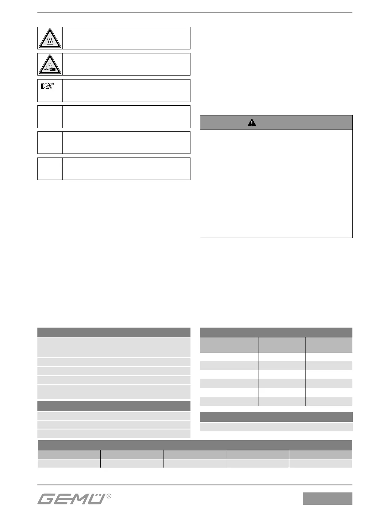
6 Technical data
2.3 Symbols used
Danger - hot surfaces!
Danger - corrosive materials!
Hand: indicates general information
and recommendations.
G Bullet point: indicates the tasks to
be performed.
® Arrow: indicates the response(s) to
tasks.
Enumeration sign
3 Definition of terms
Working medium
The medium that flows through the valve.
Control medium
The medium whose increasing or
decreasing pressure causes the valve to be
actuated and operated.
Control function
The possible actuation functions of the
valve.
4 Intended area of use
The GEMÜ 2/2-way valve is designed for
installation in piping systems. It controls
a flowing medium by being closed or
opened by a control medium.
The valve may only be used providing
the product technical criteria are
complied with (see chapter 6
"Technical Data").
The valve is also available as a control
valve.
WARNING
Use the valve only for the intended
purpose!
® Otherwise the manufacturer liability and
guarantee will be void.
G Use the valve only in accordance with
the operating conditions specified in
the contract documentation and in the
installation, operating and maintenance
instructions.
G The valve may only be used in
potentially explosive zones confirmed
in the declaration of conformity (ATEX).
5 Condition as supplied to
customer
The GEMÜ valve is supplied as a separately
packed component.
Control medium
Inert gases
Max. control pressure: 8 bar
Max. perm. temperature of control medium: 60 °C
Ambient conditions
Max. ambient temperature 60 °C
Working medium
Corrosive, inert, gaseous and liquid media which have no
negative impact on the physical and chemical properties of
the body and seal material.
Max. perm. pressure of working medium see table
Medium temperature -10 °C to 180 °C
Max. permissible viscosity 600 mm²/s (cSt)
Other versions for lower/higher temperatures and viscosities
on request.
Technical data / Actuator
Actuator
size
Filling
volume
Piston
diameter
0G1, 0M1 0.006 dm³ 28 mm
1G1, 1K1, 1M1, 1L1 0.025 dm³ 42 mm
2G1, 2K1, 2M1, 2L1 0.084 dm³ 60 mm
3G1, 3K1, 3M1, 3L1 0.245 dm³ 80 mm
4G1, 4K1 0.437 dm³ 100 mm
5G1, 5K1 0.798 dm³ 130 mm
Versions 0K, 1K, 2K, 3L and 4L are only valid for connection code 80 in combination with
valve body material C2 (only DN 15, 20, 25, 40, 50 and 65).
Maximum permissible seat leakage rate / Open-Closed-Valve
Seat seal Standard Test procedure Leakage rate Test medium
PTFE DIN EN 12266-1 P12 A air