550
36 / 44
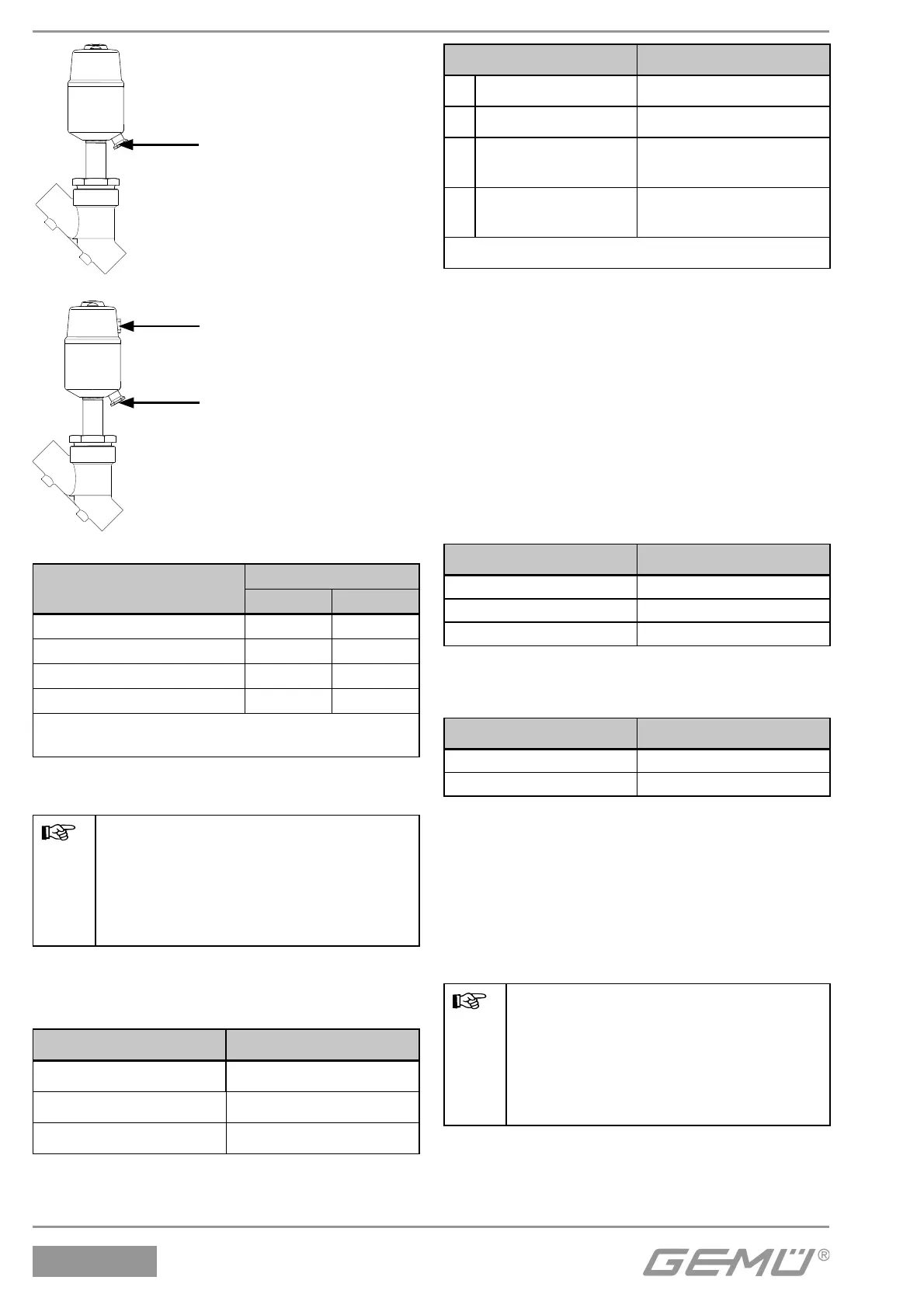
Connector 2
Connector 4
Connector 2
Control function 1
Control function 2, 3, 8
Control function
Connectors
24
1 (NC) + -
2 (NO) - +
3 (DA) + +
8 (normally open) + +
+ = available / - = not available
(for connectors 2 / 4 see graphics above)
11.4 Connecting the control medium
Important:
Connect the control medium lines
tension-free and without any bends
or knots!
Use appropriate connectors
according to the application.
Thread size for the control medium
connectors 2 and 4:
Actuator size Thread
0M5
1, 2 G 1/8
3, 4, 5 G 1/4
Control function Connectors
1 Normally closed (NC) 2: Control medium (open)
2 Normally open (NO) 4: Control medium (close)
3 Double acting (DA)
2: Control medium (open)
4: Control medium (close)
8
Double acting
(normally open)
2: Control medium (open)
4: Control medium (close)
For connectors 2 / 4 see graphics on the left
12 Assembly / disassembly of spare
parts
See also chapter 11.1 "Installing the valve"
and chapter 20 "Sectional drawing and
spare parts".
Assembly tool for disassembling /
assembling the retaining washer / regulating
cone:
Nominal size Item number
DN 15 - 25 99014983
DN 32 - 50 99032144
DN 65 - 80 99032145
Assembly valve (check valve) for
disassembling / assembling the actuator:
Thread Item number
G 1/8 99021182
G 1 /4 99021181
12.1 Disassembly of actuator
1. Move actuator A to the open position.
2. Loosen union nut a.
3. Remove actuator A from valve body 1.
4. Disconnect actuator A from control medium
lines.
Important:
After disassembly, clean all parts
of contamination (do not damage
parts). Check parts for potential
damage, replace if necessary (only
use genuine parts from GEMÜ).