550
30 / 44
7 Order data
Actuator size Code
Actuator 0 piston ø 28 mm 0
Actuator 1 piston ø 42 mm 1
Actuator 2 piston ø 60 mm 2
Actuator 3 piston ø 80 mm 3
Actuator 4 piston ø 100 mm 4
Actuator 5 piston ø 130 mm 5
Standard 1
Spring set Code
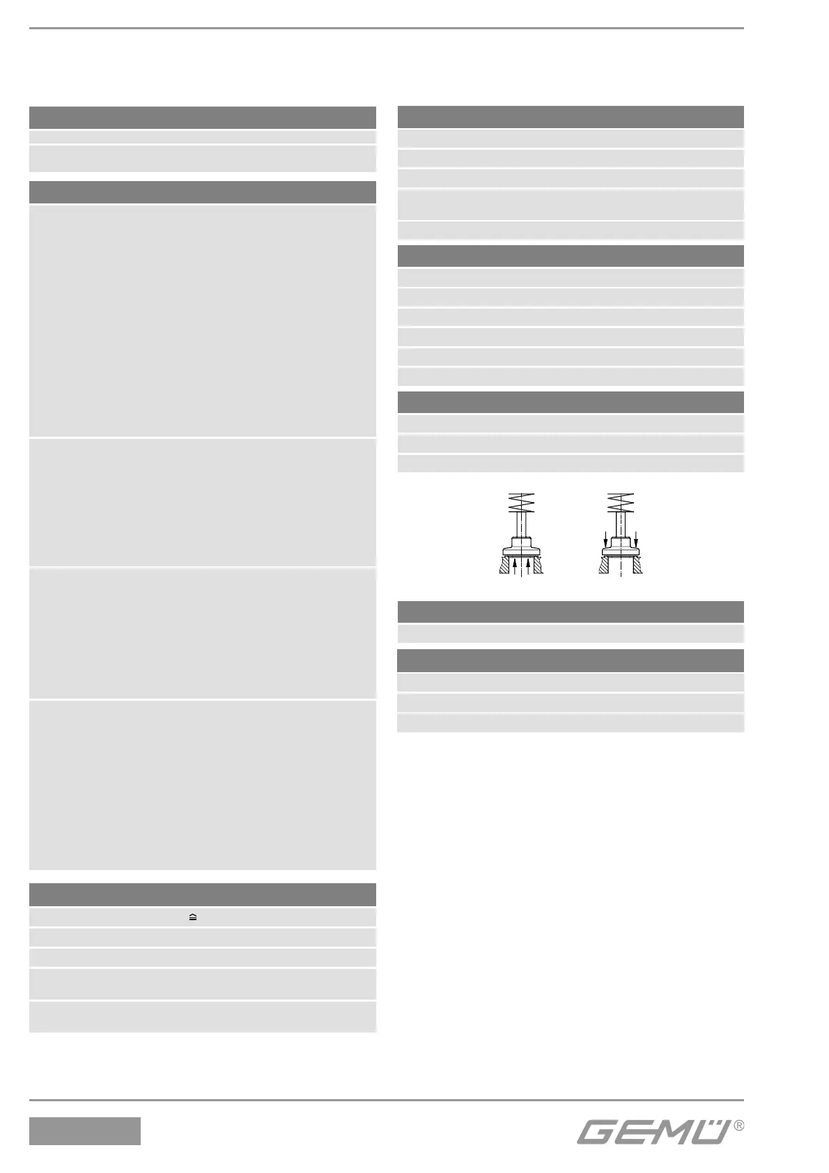
Control function Code
Normally closed (NC) 1
Normally open (NO) 2
Double acting (DA) 3
Double acting (normally open) 8*
(only for control valves)
* Regulating cone no. on request
* Preferred flow direction with incompressible media to avoid "water hammer"
Under the seat G* / K*
Over the seat M** / L**
Flow direction Code
** only control function NC
M / L
G* / K*
Body configuration Code
2/2-way body D
Angle body E
only in material code 37 (DN 15 - 50)
Versions 0K, 1K, 2K, 3L and 4L are only valid for connection code 80 in combination with
valve body material C2 (only DN 15, 20, 25, 40, 50 and 65).
Valve body material Code
1.4435 (ASTM A 351 CF3M 316L), Investment casting 34
1.4408, Investment casting 37
1.4435 (316 L), Forged body 40
1.4435, Investment casting C2*
Material equivalency 316L
* A surface finish from the order code table „K number“ must
be specified for valve body material C2.
Seat seal Code
PTFE 5
PTFE, glass fibre reinforced 5G
PTFE, USP Class VI 5P
Connection Code
Butt weld spigots
Spigots DIN 0
Spigots EN 10357 series B 16
Spigots EN 10357 series A
(formerly DIN 11850 series 2) / DIN 11866 series A 17
Spigots DIN 11850 series 3 18
Spigots SMS 3008 37
Spigots ASME BPE 59
Spigots ISO 1127 / EN 10357 series C /
DIN 11866 series B 60
Spigots ANSI/ASME B36.19M Schedule 10s 63
Spigots ANSI/ASME B36.19M Schedule 40s 65
Threaded connections
Threaded sockets DIN ISO 228 1
Threaded socket Rc ISO 7-1,
EN 10226-1, JIS B 0203, BS 21,
end-to-end dimension ETE DIN 3202-4 series M8 3C
Threaded spigots DIN ISO 228 9
Threaded sockets NPT
length DIN 3202-4 series M8 3D
Flanges
Flanges EN 1092 / PN25 / form B, 10
length EN 558, series 1
Flanges EN 1092 / PN25 /form B, 13
length see body dimensions
Flanges ANSI Class 125/150 RF, 47
length see body dimensions
Clamp connections
Clamps ASME BPE for pipe ASME BPE, 80
length ASME BPE
Clamps DIN 32676 series B for pipe EN ISO 1127, 82
length EN 558, series 1
Clamps DIN 32676 series A for pipe DIN 11850, 86
length EN 558, series 1
Clamps ASME BPE for pipe ASME BPE, 88
length EN 558, series 1