27 / 44
550
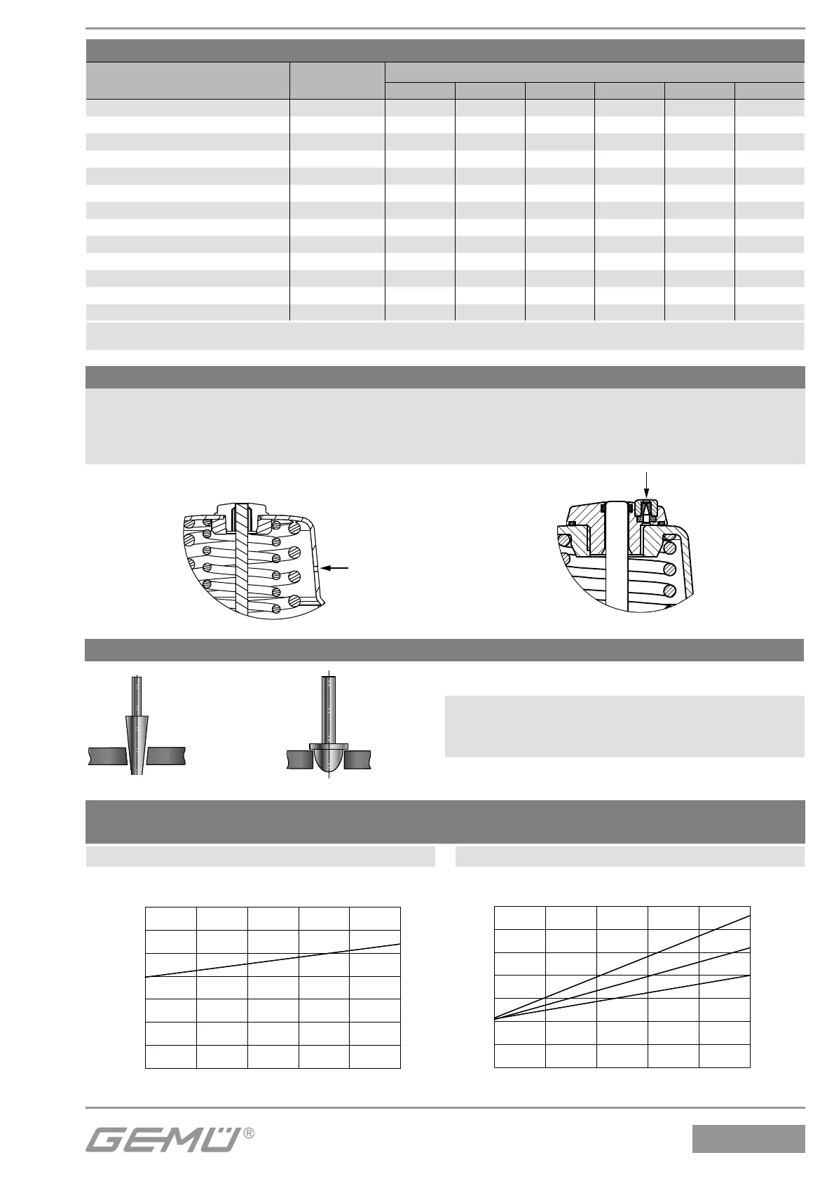
Bleed hole in the actuator
To bleed the control medium, the pneumatic actuator has a bleed hole that is located on the side of the actuator housing (con-
trol function normally closed). In certain areas of application (e.g. the foodstuff industry), dirty water or cleaning media could
enter through this bleed hole and penetrate the actuator, thereby adversely affecting correct operation. A special bleed system
with lip check valve is available for these applications, which prevents such functional impairment. The bleed hole at the side is
then closed.
Standard bleed hole Special bleed system K no. 6996
Note:
Regulating needle: RAxxx - RCxxx (reduced valve seat)
Regulating cone: DN 15 - DN 50
Regulating cone
Control valve
Regulating needle
Operating pressure / Control pressure characteristics
Control function 1: normally closed (NC) / Flow direction: over the seat
Actuator size 0M1
Min. control pressure dependent on operating pressure
Actuator size 1M1
Min. control pressure dependent on operating pressure
0
1
24
6810
2
3
4
5
6
7
Steuerdruck [bar]
Betriebsdruck [bar]
DN 6 / 8 / 10 / 15
0
1
246
810
2
3
4
5
6
7
DN 20
Steuerdruck [bar]
Betriebsdruck [bar]
DN 8-15
DN 25
Operating pressure [bar]
Control pressure [bar]
Control pressure [bar]
Operating pressure [bar]
Pressure / temperature correlation for angle seat globe valve bodies
Connection
code
Material
code
Max. allowable operating pressures in bar at temperature °C*
RT 100 150 200 250 300
1, 9, 17, 37, 60, 63, 3C, 3D 37 25.0 23.8 21.4 18.9 17.5 16.1
0, 16, 17, 37, 59, 60, 65 34 25.0 24.5 22.4 20.3 18.2 16.1
13 (DN 15 - DN 50) 34 25.0 23.6 21.5 19.8 18.6 17.2
80, 88 (DN 15 - DN 40) 34 25.0 21.2 19.3** - - -
80, 88 (DN 50 - DN 80) 34 16.0 16.0 16.0** - - -
82 (DN 15 - DN 32) 34 25.0 21.2 19.3** - - -
82 (DN 40 - DN 65) 34 16.0 16.0 16.0** - - -
86 (DN 15 - DN 40) 34 25.0 21.2 19.3** - - -
86 (DN 50 - DN 65) 34 16.0 16.0 16.0** - - -
10 (DN 15 - DN 50) 37 25.0 25.0 22.7 21.0 19.8 18.5
47 (DN 15 - DN 50) 34 15.9 13.3 12.0 11.1 10.2 9.7
0, 16, 17, 59, 60 40 25.0 20.6 18.7 17.1 15.8 14.8
17, 59, 60 C2 25.0 21.2 19.3 17.9 16.8 15.9
* The valves can be used down to -10°C ** max. temperature 140 °C RT = Room Temperature
All pressures are gauge pressures.

 Loading...


