550
34 / 44
Installation location:
CAUTION
G Do not apply external force to the valve.
G Choose the installation location so that
the valve cannot be used as a foothold
(climbing aid).
G Lay the pipeline so that the valve body
is protected against transverse and
bending forces, and also vibrations and
tension.
G Only mount the valve between
matching aligned pipes.
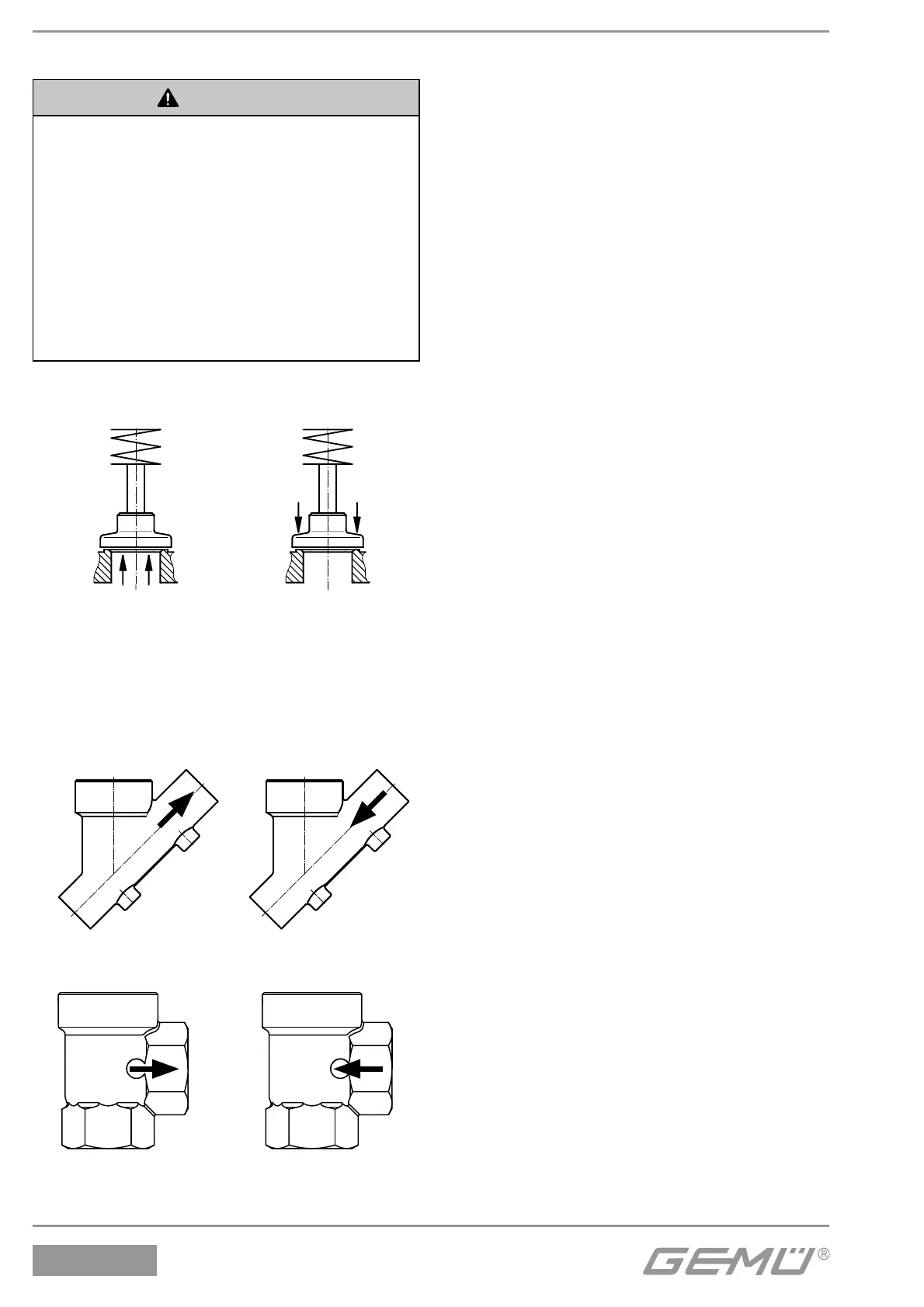
Direction of the working medium:
Flow direction:
G* M
Flow under the seat Flow over the seat
* Preferred flow direction with
incompressible liquid media
to avoid "water hammer".
The flow direction is indicated by an
arrow on the valve body:
2/2-way body
Flow under the seat
2/2-way body
Flow over the seat
Angle body
Flow under the seat
Angle body
Flow over the seat
Installation:
1. Ensure the suitability of the valve for
each respective use. The valve must
be appropriate for the piping system
operating conditions (medium, medium
concentration, temperature and
pressure) and the prevailing ambient
conditions. Check the technical data of
the valve and the materials.
2. Shut off plant or plant component.
3. Secure against recommissioning.
4. Depressurize the plant or plant component.
5. Completely drain the plant (or plant
component) and let it cool down until
the temperature is below the media
vaporization temperature and scalding
can be ruled out.
6. Correctly decontaminate, rinse and ventilate
the plant or plant component.
Installation - Butt weld spigots:
1. Adhere to good welding practices!
2. Disassemble the actuator before welding the
valve body into the pipeline (see chapter
12.1).
3. Allow butt weld spigots to cool down.
4. Reassemble the valve body and the actuator
(see chapter 12.3).
Installation - Clamp connections:
G When assembling clamp connections,
insert a gasket between the body clamp
and the adjacent piping clamp and join
them using the appropriate clamp fitting.
The gasket and the clamp for clamp
connections are not included in the scope
of delivery.
Installation - Threaded connections:
G Screw the threaded connections into the
piping in accordance with valid standards.
G Screw the valve body into the piping, use
appropriate thread sealant. The thread
sealant is not included in the scope of
delivery.