54 GSM19 Series Magnetometers - Version 7
GEM Systems, Inc. Advanced Magnetometers
For more technical information, visit www.gemsys.ca
5.4.5 Evaluating Signal Quality
Each mode, which includes the magnetic field measurement, has a signal quality indicator that is
displayed in text. It is stored in memory, and it can be recovered using the SEND or File Review
functions. It is a number presented in the form xy, where x and y are between 0 and 9.
• X is associated with measurement time and is a sort of gradient indicator.
• 9 means max measurement time was accomplished.
• 0 means measurement was too short.
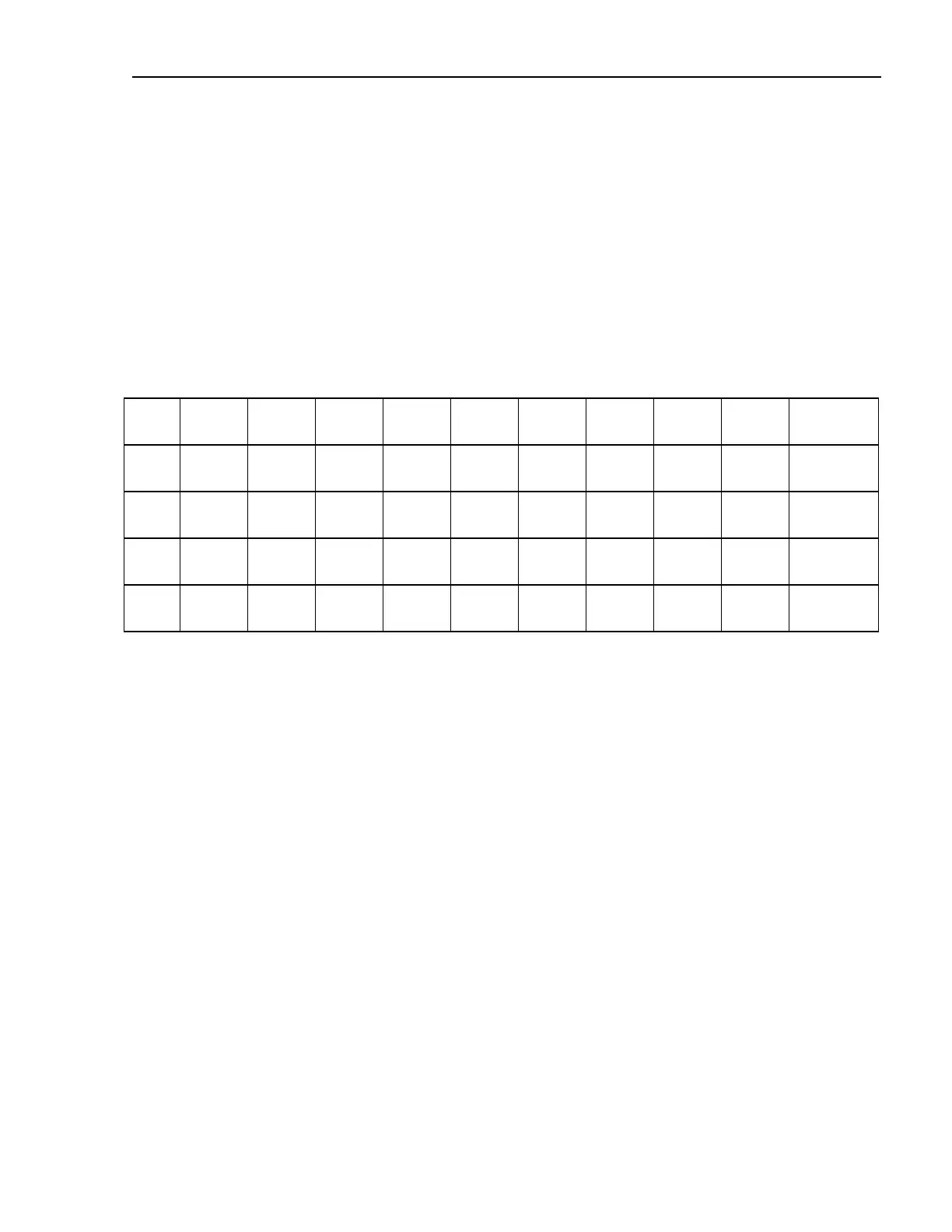
0
1 2 3 4 5 6 7 8 9
>=1s <100
ms
<200
ms
<300
ms
<400
ms
<500
ms
<600
ms
<700
ms
<800
ms
<900
ms
>=900ms
0.5s <50ms <100
ms
<150
ms
<200
ms
<250
ms
<300
ms
<350
ms
<400
ms
<450
ms
>=450ms
0.2s <35ms <40ms <60ms <75ms <90ms <115
ms
<130
ms
<145
ms
<158
ms
>=158ms
0.1s <34ms 38ms <42ms <46ms <50ms <54ms <58ms 62ms <66ms >=66ms
Table 2: Definition of X
The numbers in the table represent the measurement time. The value of X is obtained differently
depending on the cycling rate and the accomplished measuring time.
• Y represents the area under signal amplitude coincident with the time of measurement.
• 9 means optimal conditions.
• 0 means unacceptable reading.
• x=0 causes y=0 but not vice versa.