www.gemu-group.com 43 / 56 GEMÜ 1235 / 1236
24V, 3S, 4S
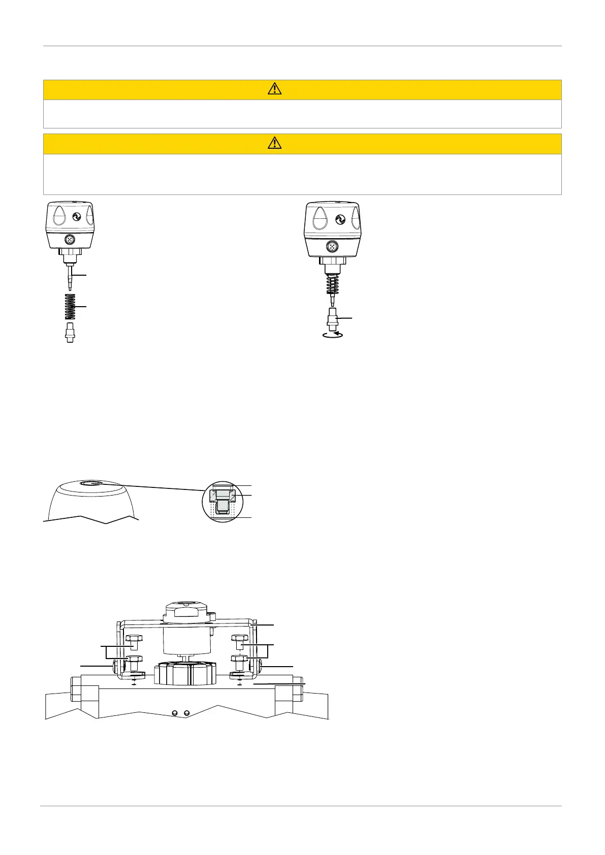
10.3 Mounting kit assembly on electrical position indicator
CAUTION
Do not scratch the spindle!
▶ A damaged spindle surface may cause failure of the travel sensor.
CAUTION
Pretensioned spring!
▶ Damage to the device.
● Slowly release the tension in the spring.
1. Pull out spindle 1 as far as it will go.
2. Push spring 2 over spindle 1.
3. Mount operating spindle 3.
4. Push in spindle 1 until it pushes against spring 2.
10.4 Threaded adapter assembly (linear actuator)
With some mounting kits, it is necessary to install a threaded adapter as well. This threaded adapter is enclosed with the re-
quired mounting kits. Valves with a normally open and double acting control function (code 2+3) also include additional O-rings
(1+2).
1. Move the actuator to the closed position.
2. Place O-rings 1 and 2 into threaded adapter 3.
3. Screw threaded adapter 3 into the actuator opening as far as it will go and tighten.
10.5 Mounting kit assembly (quarter turn actuator)
1. Adjust the mounting bracket to the required borehole pattern.
ð To do this, loosen the side screws 5 and set the retaining feet onto the thread of the actuator, and install it using screws
4.
2. Secure the bracket 3 to the retaining feet as shown. In doing so, the tap shaft must sit free of play in the shaft of the actu-
ator.
10 Assembly and installation