www.gemu-group.com 47 / 56 GEMÜ 1235 / 1236
24V, 3S, 4S
12 Programming the end positions
The end positions must be programmed under the following conditions:
- Retrofitting the electrical position indicator
- Replacing the actuator
- Replacing the diaphragm
If electrical position indicators have been fitted to the process valve at the factory, the end positions will already have been pro-
grammed.
The end positions can be programmed as follows (depending on the order version):
- On-site programming
- Programming input (pin 5)
- Communication interface
When programming via the communication interface, automatic programming is recommended.
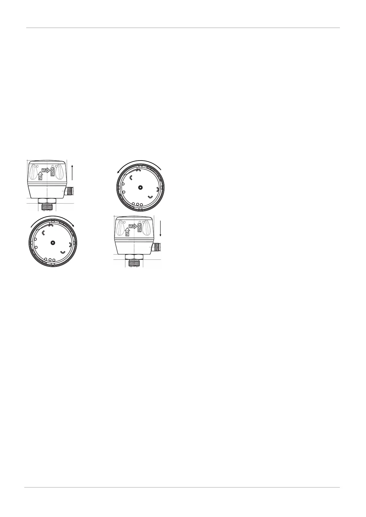
12.1 On-site end position programming
CLOSED
ERROR
OPEN
PWR/COM
FA U LT
CLOSED
ERROR
OPEN
PWR/COM
FA U LT
1. Pull the housing cover of the electrical position indic-
ator up (approx. 2 mm).
2. Turn the housing cover anticlockwise (until it stops).
3. Electrical position indicator is in the programming
mode.
ð OPEN and CLOSED LEDs flash alternately
ð High visibility LED flashes alternately green / or-
ange
4. Open valve until end position is reached.
5. Close valve until end position is reached.
6. Turn the housing cover back clockwise and press it
down.
ð The end positions are set.
12 Programming the end positions