www.gemu-group.com44 / 56GEMÜ 1235 / 1236
24V, 3S, 4S
10 Assembly and installation
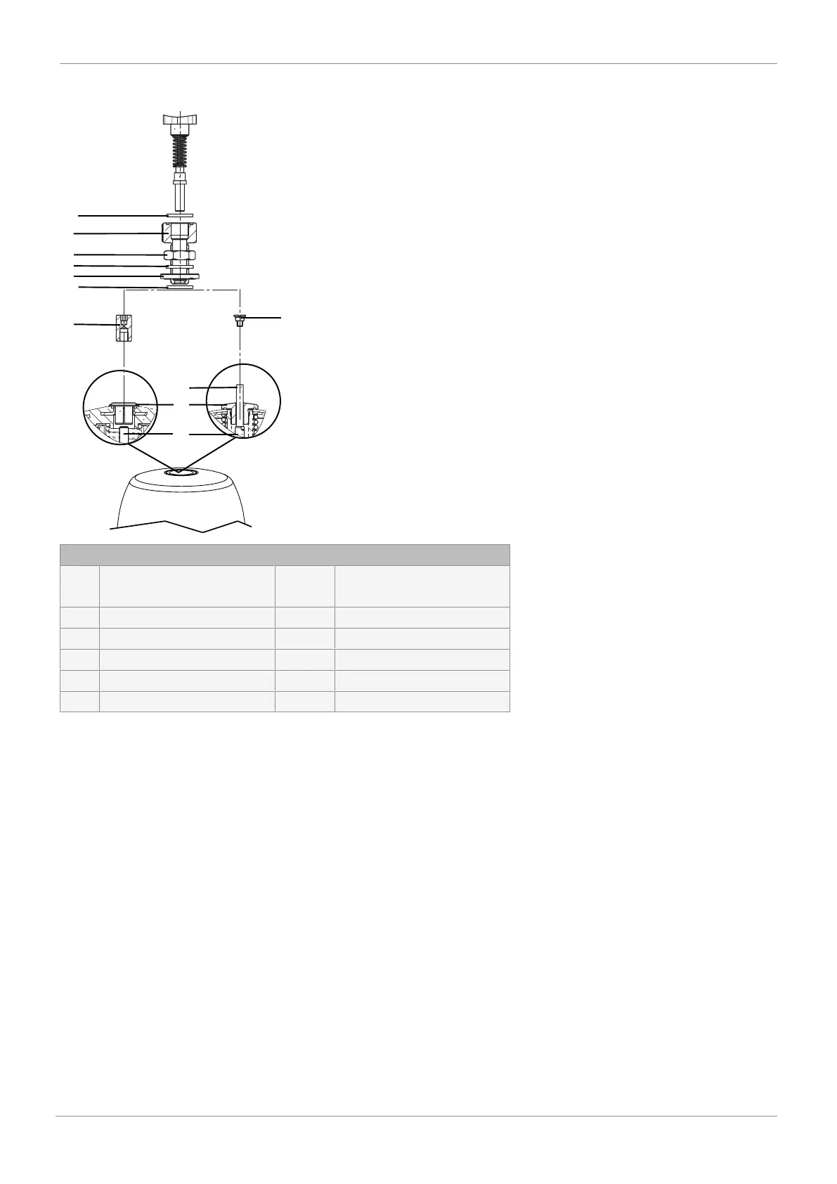
10.6 Assembling the stroke limiter (linear actuator)
5
5
4
3
2
1
6
8
9
7.1
7.2
Option1
Option2
1. Screw distance piece 5 onto/into actuator spindle 6.
2. Move the actuator to the closed position.
3. Insert the O-ring 7.1 in the stroke limiter 1.
4. Insert the O-ring 7.2 in the washer 4.
5. Screw stroke limiter 1 with nut 2, seal 3 and washer
4 into the actuator opening.
6. Set stroke limiter 1 to the required stroke.
7. Make sure that the minimum stroke is reached.
8. Secure stroke limiter 1 with nut 2.
Key
1 Stroke limiter 7.1
1)
7.2
1)
O-ring
2 Nut 8 Protective cap
3
1)
Seal 9 Position indicator
4
1)
Washer 10 Operating bush
5
2)
Distance piece 11 Spindle
6 Actuator spindle 12 Travel sensor
1) Only available for valves with the NO and DA control functions.
2) Only included in required mounting kits. The design depends on the valve.