www.gemu-group.com46 / 56GEMÜ 1235 / 1236
24V, 3S, 4S
11 Electrical connection
10.8 Installing the electrical position indicator (quarter turn actuator)
CAUTION
Incorrect installation of the product.
▶ Damage to the housing.
● Only tighten the product using the spanner flats provided for this purpose.
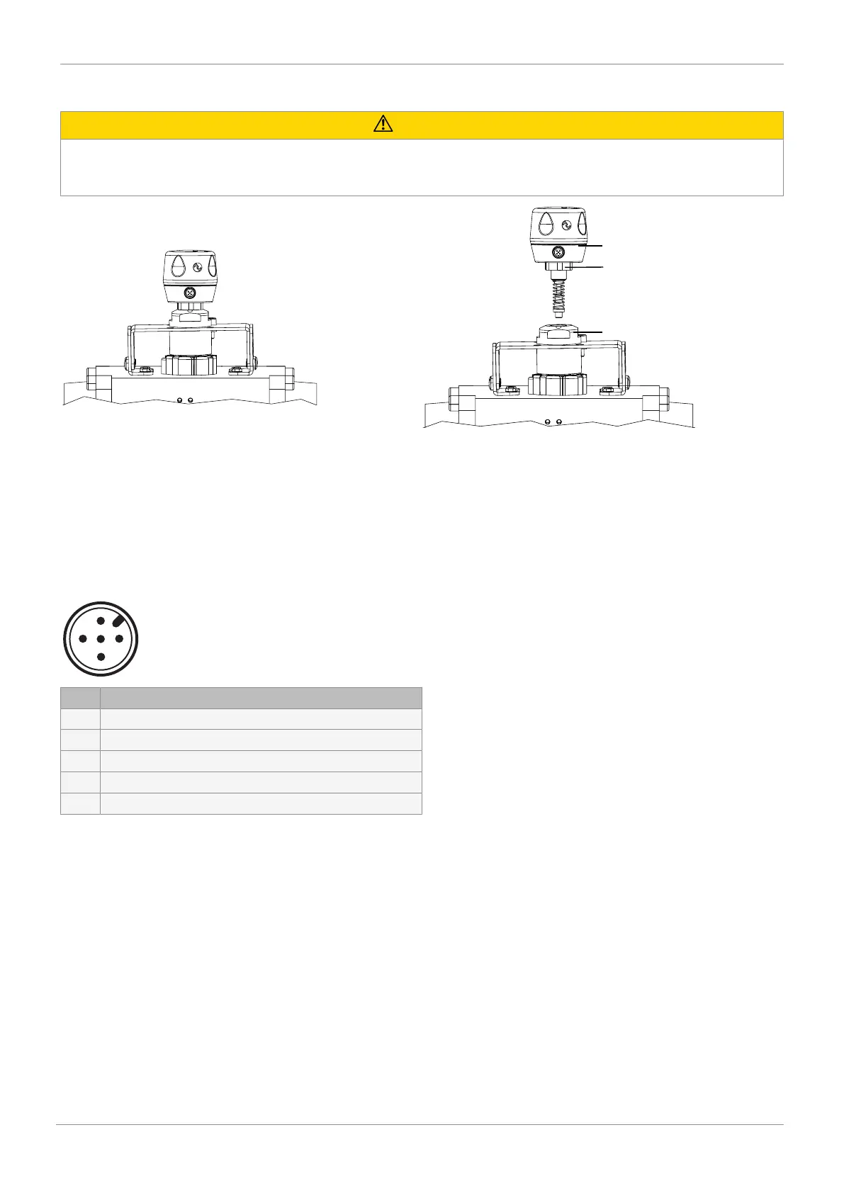
1. Screw the electrical position indicator 6 onto the adapter 7.
2. Use the spanner flat 8 (WAF 27) of the travel sensor to tighten the electrical position indicator.
3. Turn the housing clockwise to align the pneumatic or electrical connections.
4. Initialize the product.
11 Electrical connection
11.1 24 V, ordering option device version, code 3S/4S/3X/4X
Description
1 U, 24 V DC, supply voltage
2 U, GND
3 24 V DC, Open end position output
4 n. c.
5 24 V DC, Closed end position output