Section 5 Disassembly
68 Diagnostic Repair Manual
7. Remove the M8 bolt from the rear bearing carrier.
(Figure 5-11, Item 15)
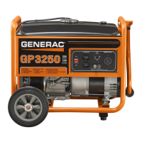
8. Remove the exhaust clamp. (Figure 5-11, Item 35)
9. Remove the muffler. (Figure 5-11, Item 6)
Figure 5-5. Remove Muffler
Remove Stator
1. Disconnect wire 4 and wire 0 from the brush
assembly. (Figure 5-11, Item 21)
2. Remove the brush assembly. Remove the four
stator hold down bolts. (Figure 5-11, Item 12)
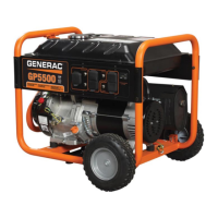
3. Lift the rear end of the alternator up to clear the
muffler frame from the rubber alternator mount.
Place a 2x4 under the front bearing carrier for
support.
4. Using a rubber mallet carefully remove the rear
bearing carrier. (Figure 5-11, Item 4)
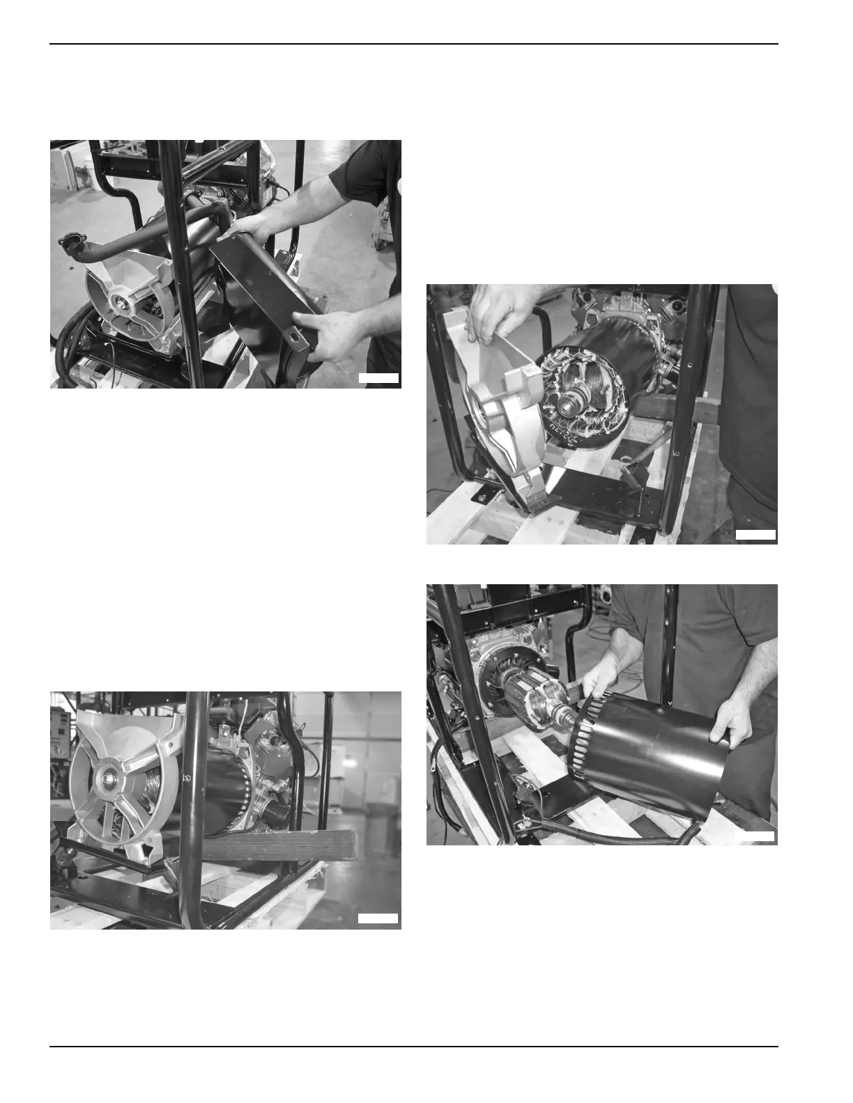
5. Rotate the rotor so that the steel laminations face
the top and bottom.
6. Remove the stator can.
Figure 5-6. Support Alternator
Remove Rotor
1. Remove rotor bolt. (Figure 5-11, Item 11)
2. Cut 2.5 inches from the hex head end of the rotor
bolt.
3. Slot the end of the bolt to suit a flat blade
screwdriver.
4. Slide the rotor bolt back through the rotor and use
a screwdriver to screw it into the crankshaft.
5. Use a 3” M12 x 1.75 bolt to screw into the rotor.
6. Apply torque to the 3” bolt until the taper breaks.
NOTE: If necessary use a rubber mallet on the end of
the rotor shaft to break the taper when torque is applied
to the 3” bolt.
Figure 5-7. Remove Bearing Carrier
Figure 5-8. Remove Stator

 Loading...